This page is not compatible with Internet Explorer.
For security reasons, we recommend that you use an up-to-date browser, such as Microsoft Edge, Google Chrome, Safari, or Mozilla Firefox.
Quality Control in Injection Molding and Plastics
Using Industrial Computed Tomography
Quality Control in Injection Molding and Plastics
Injection molding provides the unmatched ability of producing high numbers of complex plastic parts very quickly with outstanding quality. This is why injection molding has been the standard for decades to produce high-volume, durable products. As the volumes grow, so does the competition. To stay competitive, a manufacturer needs to meet the numerous and challenging demands on the quality of its products.
The Challenge
Typical injection molding defects are entrapped air, porosity, sink marks, joint lines, deformation, and misaligned fiber orientations. A great example are automotive connectors where complexity increases, tolerances get tighter and the goal is zero defect production. Gas-assisted foam molding as well as miniaturization leads to parts that traditional inspection methods cannot cope with.
The Volume Graphics Solution: Using Computed Tomography in Plastic and Injection Molding Process Chains
Computed tomography (CT) measurements provide the unique ability to get a full understanding of a part's quality. It does not stop at surface data from easily accessible geometries, which also conventional coordinate measuring machines (CMM) or optical scanners deliver. CT gives you true insights such as the detection and analysis of injection molding defects, and the ability to acquire all dimensions even inside the parts. Surface characteristics such as color, transparency, or reflectivity are no problem for CT scanners. Full volume measurement provides the quickest possible path from design to manufacturing.
Volume Graphics supports all phases of injection molding from part design and process simulation to inline inspection. Dimensional analyses of simulation models can help to find the best parameter set as an input for the first mold. First article inspection of dimensions, form, and shape are rounded up by the ability to qualify and quantify injection molding defects such as porosity and inclusions as well as fiber orientations and volume fractions. Results of fiber and porosity analyses can be mapped onto PATRAN ® and NASTRAN ® volume meshes for exchange with simulation solutions such as Digimat.
Our Manufacturing Geometry Correction Module connects the metrology department with the mold maker and enables an easy way to identify part warpage and export compensated geometry to the tooling department for mold correction. Finally, all parameters such as dimensions, wall thicknesses, and GD&T analyses, as well as porosity & inclusions are even available from our inline inspection solution for 24/7 production. Volume Graphics uniquely connects the CAD and PMI data with simulation and tooling.

Advantages
With Volume Graphics software, you get a maximum of functionality in one tool that covers all tasks and can easily be integrated in your daily workflow:
Accurate
Accurate
- Unique locally adaptive and subvoxel precise surface determination, with accuracy verified in numerous studies
- Surface representation directly on the CT data—no loss of accuracy from conversion to a surface mesh
- PTB and NIST verified fitting of geometry elements on CT data
Comprehensive
Comprehensive
- Comprehensive scope of functionalities for metrology, mold cavity correction, fiber compound analyses and defect detection in one software
- Measurement of inner and outer geometries, no spray, no stickers needed
- Measurement in single material, multi material and even assemblies
- Handling of point cloud, mesh, and voxel data
Connected
Connected
- Import of PMI measurement plans directly from CAD models
- Fully digital tool correction workflow between design, metrology, and tooling
- Mapping of fiber orientations and fiber volume fractions onto existing volume meshes for FEM simulation or validation of molding simulations
- Communicates with external quality systems through its reporting engine
The Volume Graphics Solution in Detail
Coordinate Measurement
Warpage and shrinkage in plastic injection parts need to be measured during the design and manufacturing phase. Dimensioning and GD&T analyses can be fully automated and distributed by customizable reports.
Alignments include RPS, 3-2-1, and sequential alignment, as well as best fit and feature-based fit. 2D needle and 3D color-coded plots provide an easy-to-understand and global overview, supporting manual or rule-based annotations.
All GD&T analysis types are supported. Measurement templates are universal and can be applied to CAD and CT data and also to meshes from molding simulations or optical scan data. Downstream communication is using free viewers and fully customizable Excel Reporting.
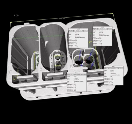
Hirschmann Automotive uses VGSTUDIO MAX to measure its connectors and their 1,200 measurement features
Wall Thickness Analyses
Wall thickness influences the behavior of the melt front and the homogeneity of the temperature in the part during the filling process and the cool down. A thorough analysis of the actual wall thickness provides more insight to potential problems resulting in warpage.
Volume Graphics provides two options for wall thickness measurement:
- Direction-based calculation to determine the distance between opposite walls, a standard with little forgiveness on angular deviations.
- Sphere-based calculation by filling the volume with maximum sized spheres, providing results for any complex geometry.
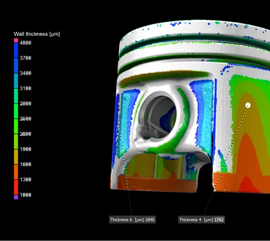
VGSTUDIO MAX shows the wall thickness color-coded directly on the surface of the piston
Porosity and Inclusion Analyses
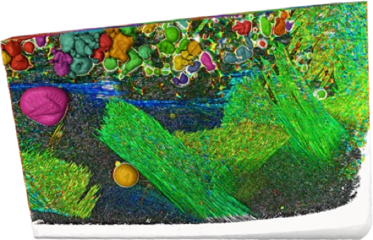
The melt front can entrap air resulting in pores, and burnt material or contaminated raw material may produce inclusions in injection-molded parts.
The porosity/inclusion analysis locates pores, holes, and inclusions and documents detailed quantitative information and statistics about these defects. The measured mean porosity can be loaded into an existing PATRAN ® or NASTRAN ® mesh to compare it with simulated injection molding results, or for use in FEM simulations. The analyses can also be exported to MAGMASOFT ® as .emv file.

The porosity/inclusion analysis locates pores, holes, and inclusions
Fiber Analyses
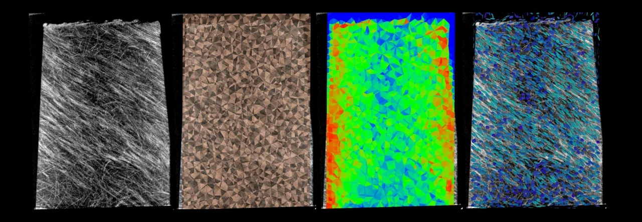
Injection molding of fiber-reinforced compounds requires the control of the fiber orientations which determine the mechanical properties of the component. Fiber orientations and fiber volume fractions can be derived from CT scans and mapped onto existing volume meshes in the PATRAN ® or NASTRAN ® format—either for direct use in FEM simulation or for validation of fiber distributions from injection molding simulations. A dedicated format for export into Digimat® is available.
VGSTUDIO MAX clearly shows the fiber orientation within the rotor blades made of light-weight, fiber-reinforced plastic composites
Tool Optimization
Injection-molded parts shrink and warp due to the material and heat distribution and cool-down behavior.
The Manufacturing Geometry Correction Module analyzes the deviation in order to export compensated surfaces for the mold maker. By adding the compensated warpage deviation to the shrinkage information, the output can be used to update and optimize the mold, with minimal tool rework. Quality control includes draft angle and curvature analyses. It can also reconstruct surface patches by shrink wrapping it to the scan or the mold.
The Manufacturing Geometry Correction Module establishes a digital workflow and communication between design, try out, the quality department and manufacturing.
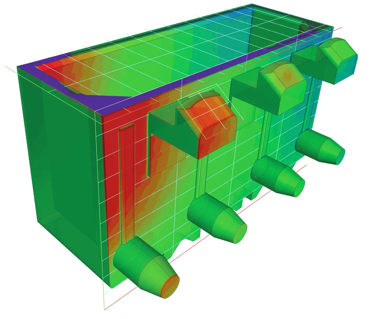
The Manufacturing Geometry Correction Module gives you a color-coded visualization that shows deviations of the manufactured part from the target model
Related Products
Additional Information
- Whitepaper "How (Not) To Digitalize Your Plastic Injection Molding Design Process"
- Using the local fiber orientation and fiber to volume fraction in μCT data to improve the simulated failure location and strain at break of Long Fiber Thermoplastic (LFT) parts (Technical Paper, Asia Pacific Conference on Non-Destructive Testing 2017)
- Using the local fiber orientation and fiber to volume fraction in μCT data to improve the simulated failure location and strain at break of Long Fiber Thermoplastic (LFT) parts (Presentation)