: Custom Path and Profile Window")
Back due to popular demand after last week's deep dive into the non-planar and rotation view, this week we will be highlighting two more views in VGSTUDIO MAX: custom path and profile window!
Custom Path View
As the name suggests, the custom path view allows us to tailor our view to our heart's desire. It is ideal for unrolling shapes that are not quite so geometric, like tubes. All we need to do is set the reference, which can be a geometry element or instrument—like a polyline.
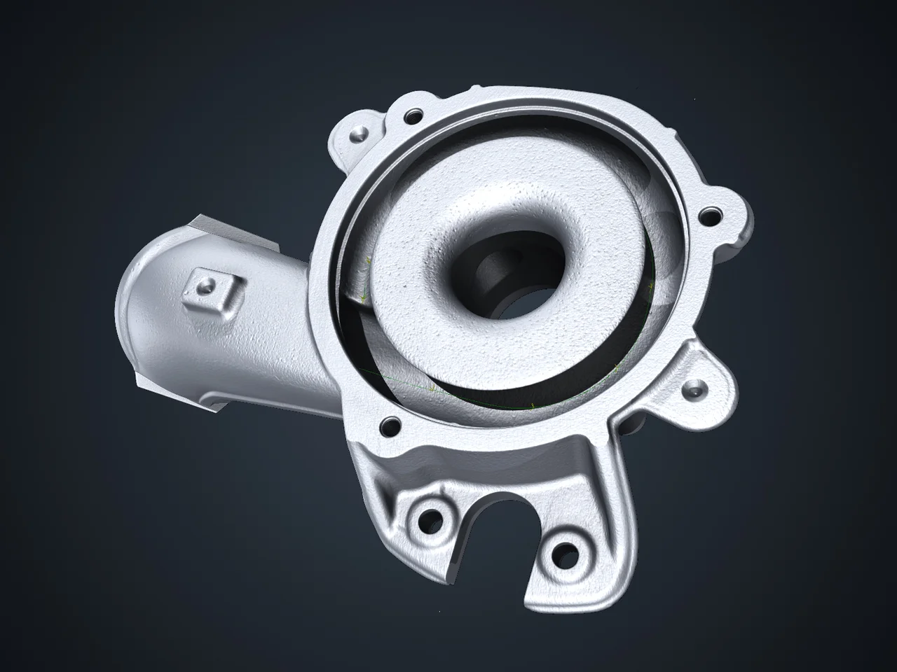
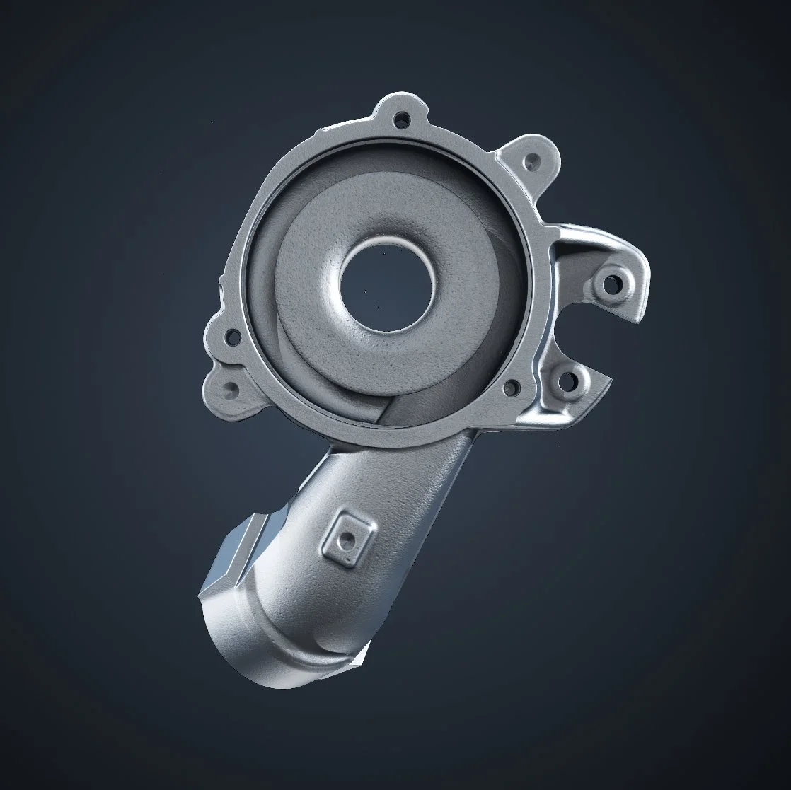
Let's take a turbocharger, which is very conveniently shaped for our purposes. Before we begin, a few words on its shape and structure.
What Is a Turbocharger?
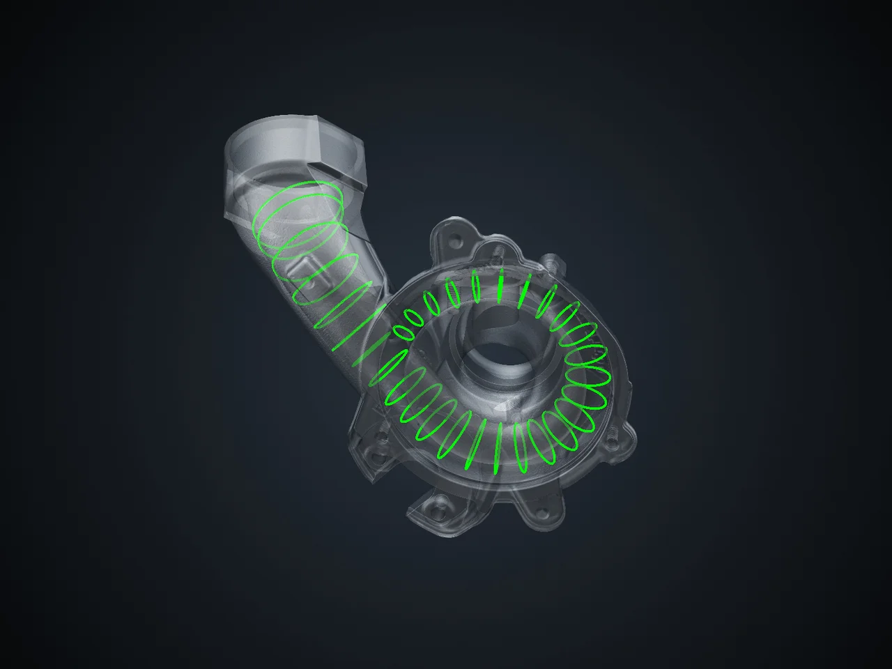
A turbocharger is a turbine-driven device that increases the power output of an internal combustion engine by forcing extra compressed air into the combustion chamber. The central housing swirls into a snail-like shape while the tube narrows as it moves inward. This pushes extra air into the chamber.

We will trace a reference path along this tube using a polyline.
Here is a 2D view of our polyline.
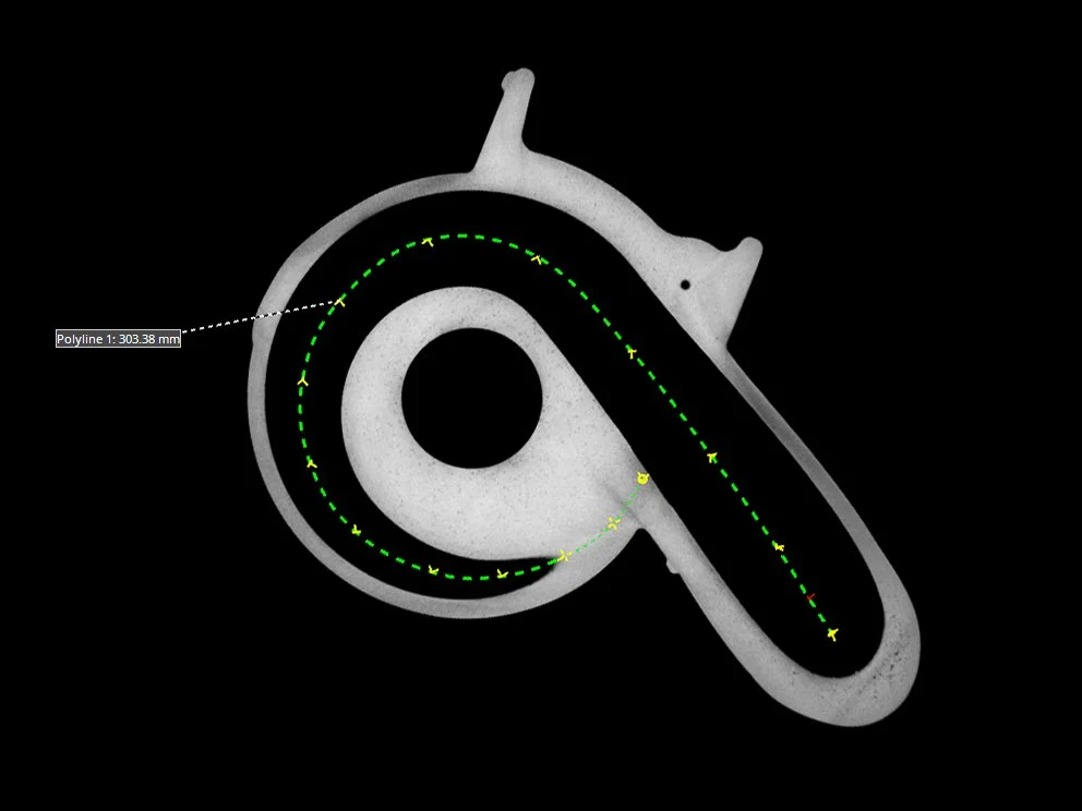
2D view of a polyline along the empty space in the tube of the turbocharger
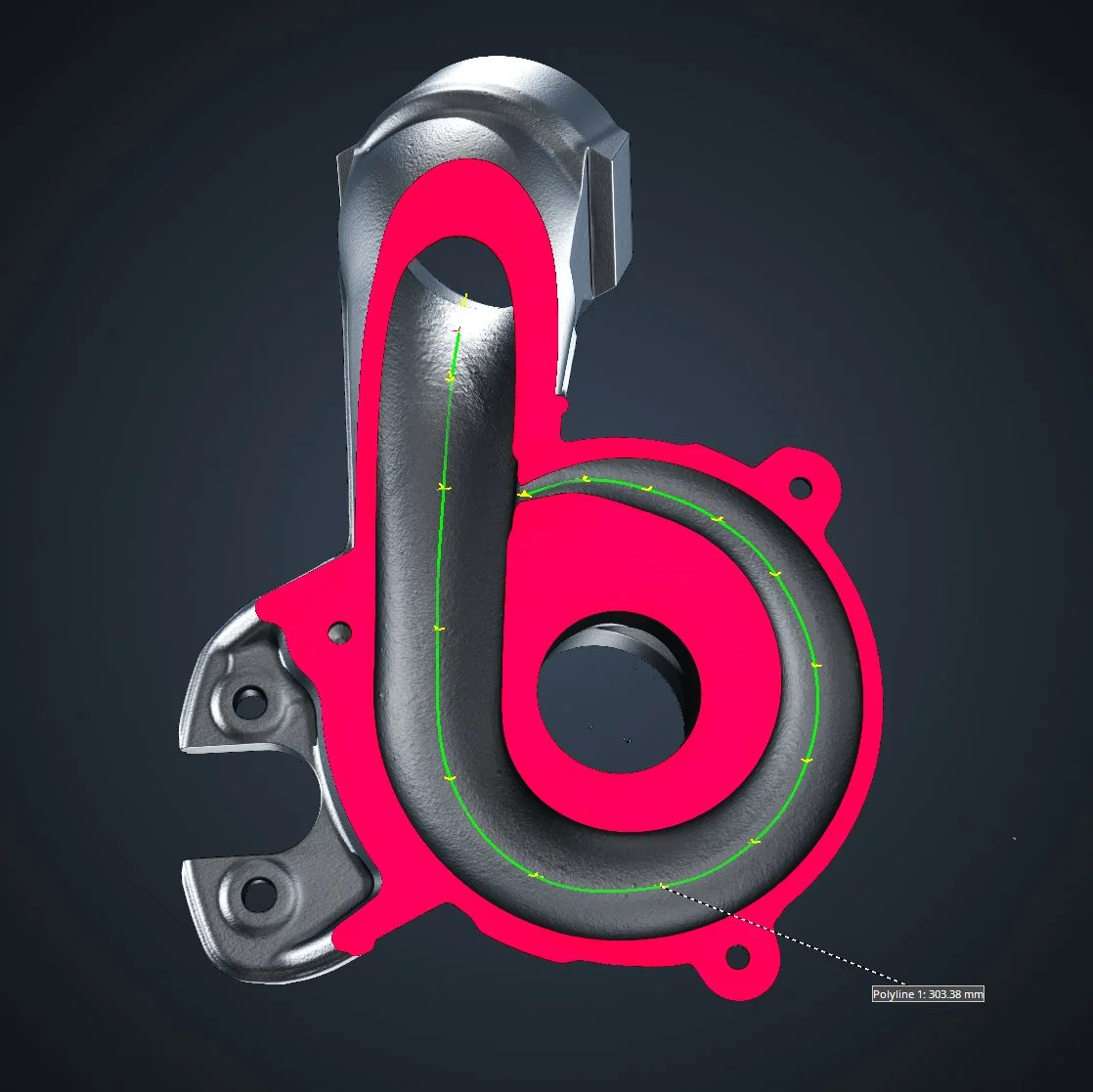
3D view of our polyline
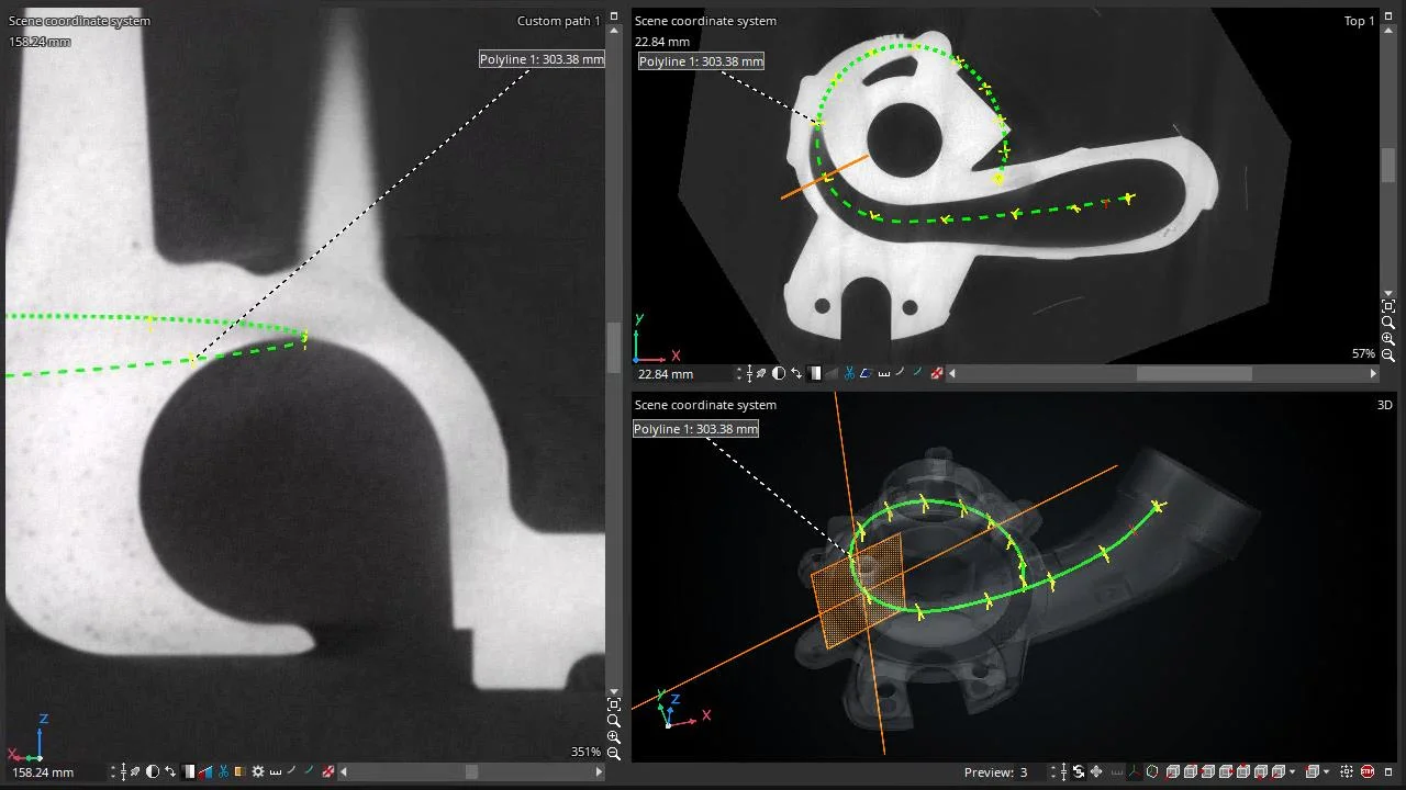
The polyline (green) defines the custom path view (left), while the navigation plane of the custom path view (orange) is visible in the 2D and 3D views (right)
Based on this reference path, we can fit circles at different positions of the snail canal to create cross sections.
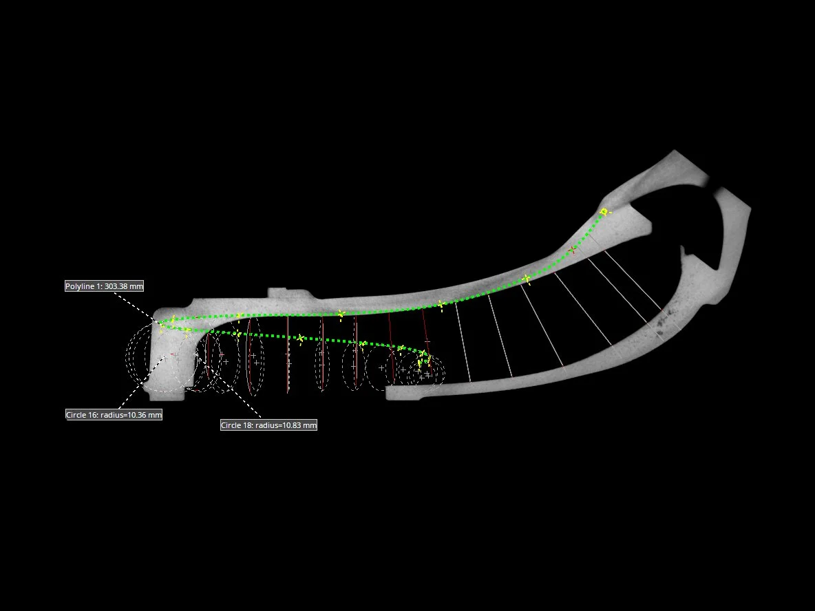
"Climbing" circles in the 2D view
Time-lapse video: creating circles inside the rotation view
(Tip: check it out in full-screen to catch all the details!)
A closer look at the circles in the turbocharger
From there, we can import the cross sections into a CAD software for reverse engineering.
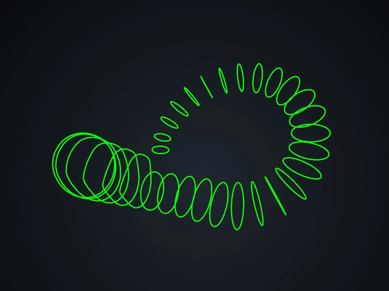
Green circles only, with the turbocharger set to transparent
We can try this out on a lot of things, such as this nifty pilot's helmet.
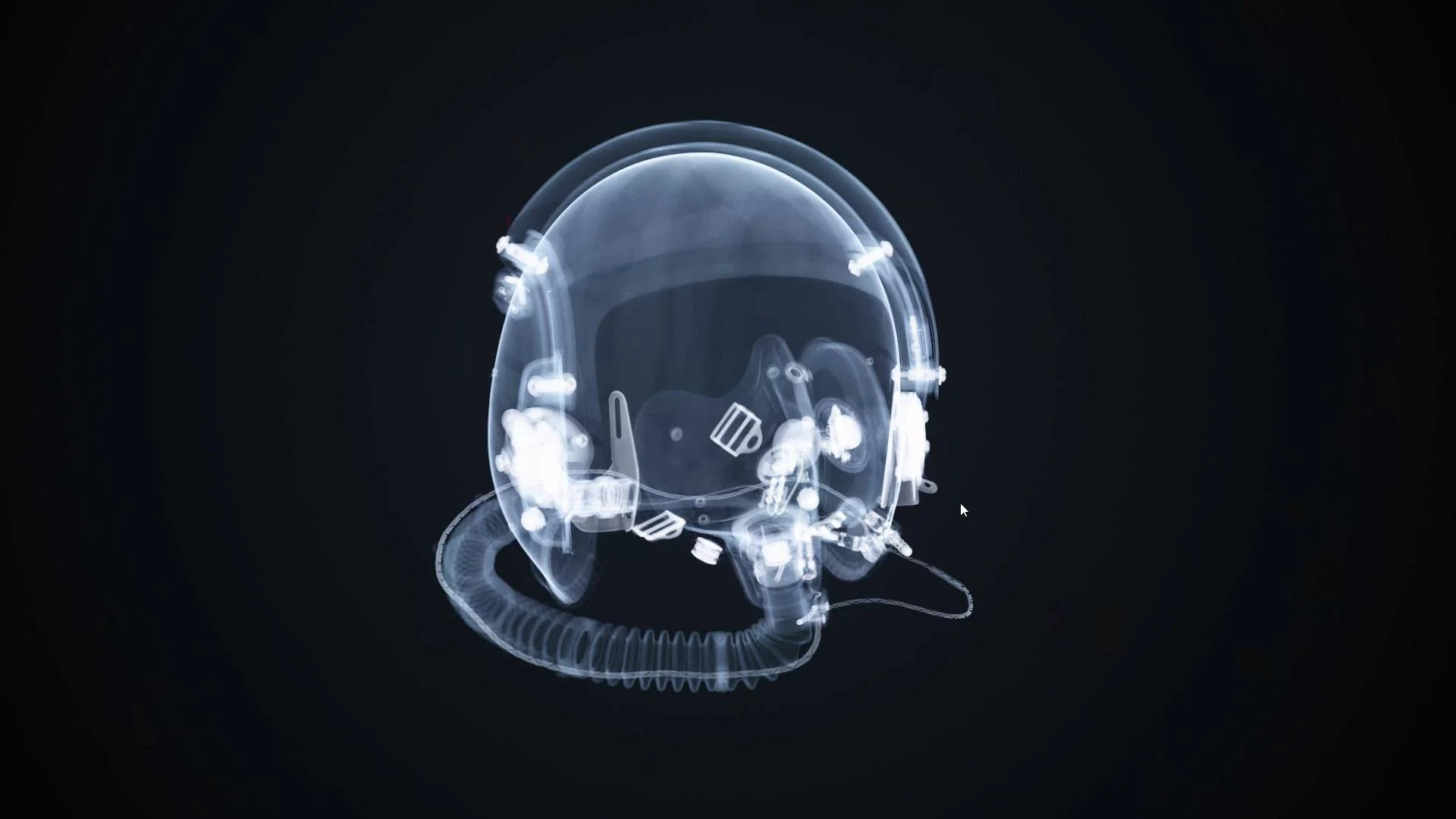
A pilot helmet in all its semi-transparent glory
That breathing tube looks mighty tempting, but if you look closely, you can see a cable inside the breathing tube. Let's aim for that.
As with the turbocharger, we can set a polyline across the cable.
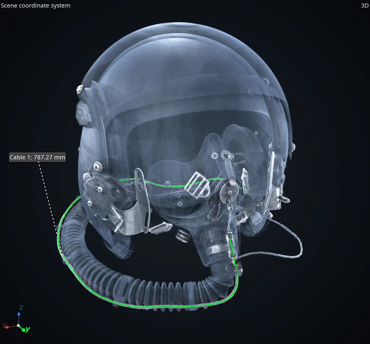
Green indicates the polyline we have set
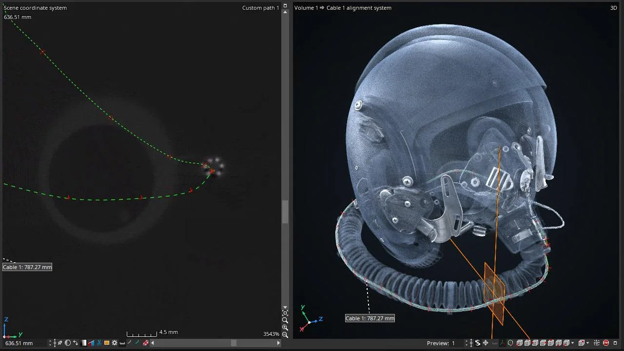
Watch the cable dance! It feels a bit like a roller coaster, so move along the path and enjoy the ride! We can even loop the path when we're done.
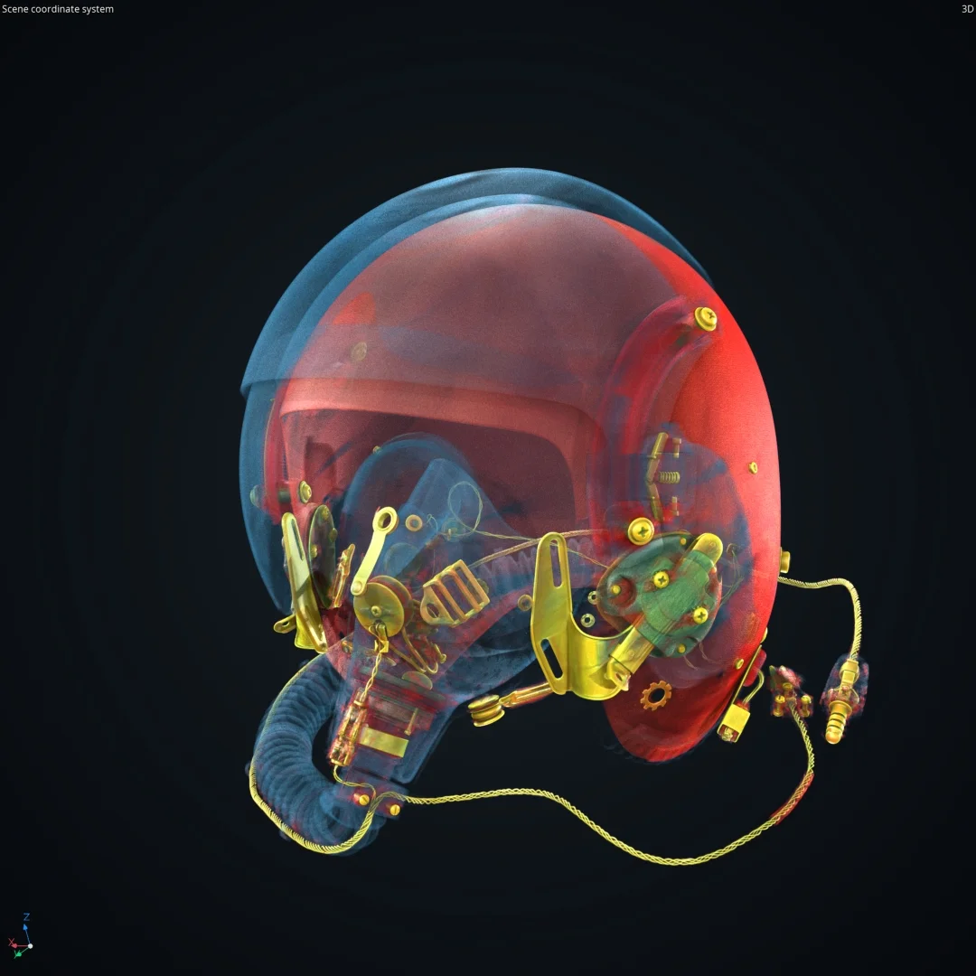
As a small reward, we can treat ourselves to a bit of color here.
Now let's switch gears completely and talk about gray value profiles.
(Gray Value) Profile Window
The profile window can either be accessed through the quad profile or created in the layout editor. It allows us to gain insight into the gray values along a line. This picks up on key differences we often miss, as our eyes automatically adjust our perception of light and contrast based on a variety of factors, such surrounding color and objects.
Don't believe us? Just look at the checker shadow illusion!
Don't Let Your Perception Fool You!
The checker shadow illusion is a classic example of how our eyes can play tricks on us. Because of the shading and placement of the cylinder, we perceive squares A and B to be different colors. But are they really?
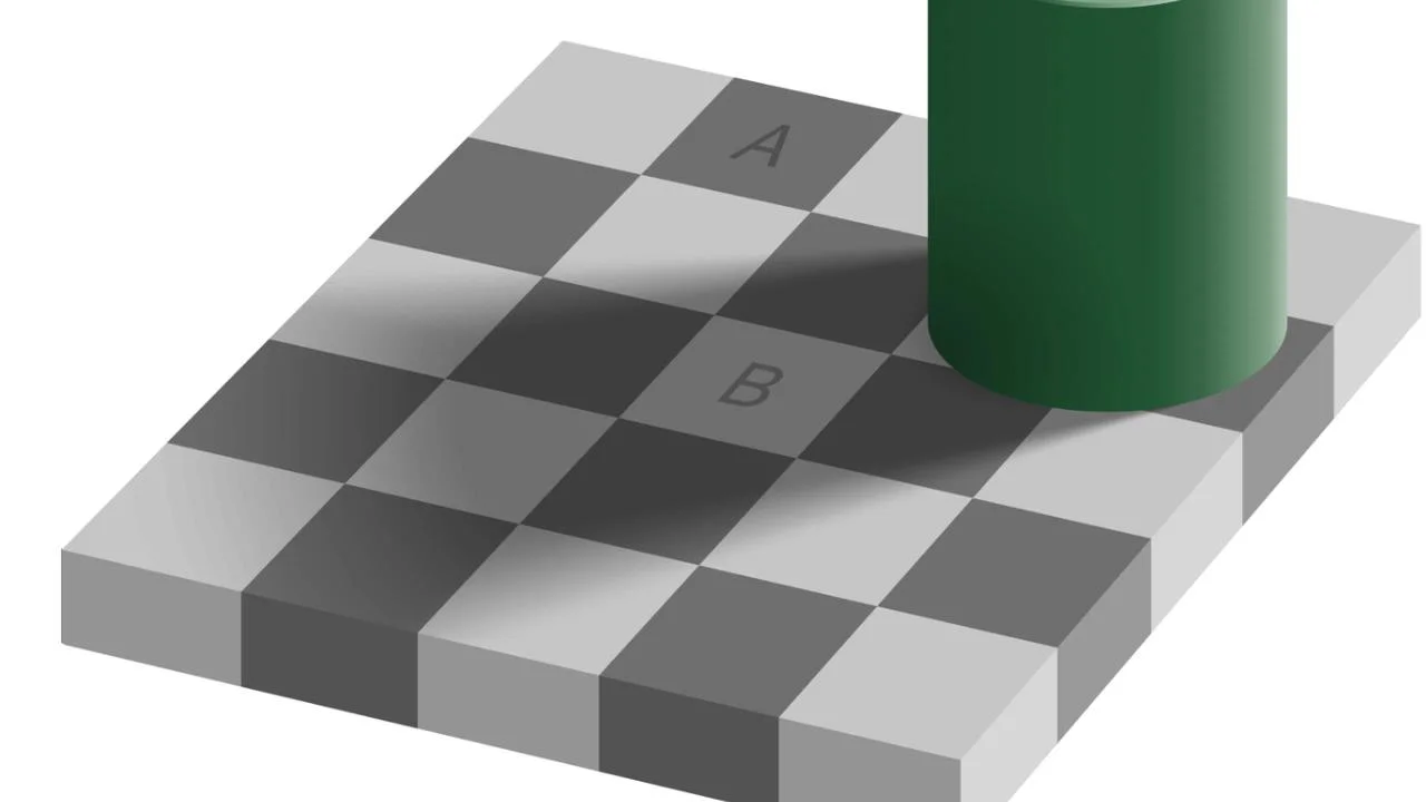
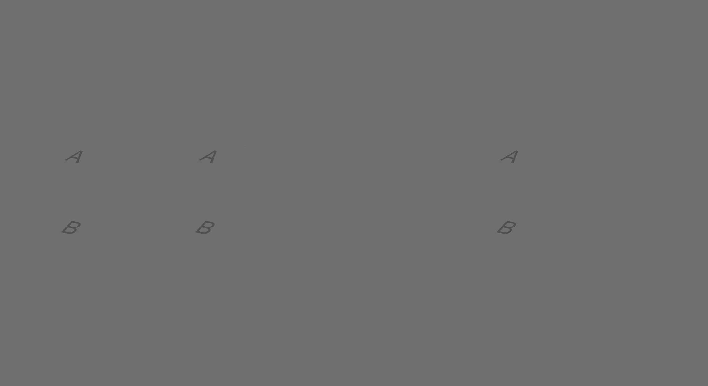
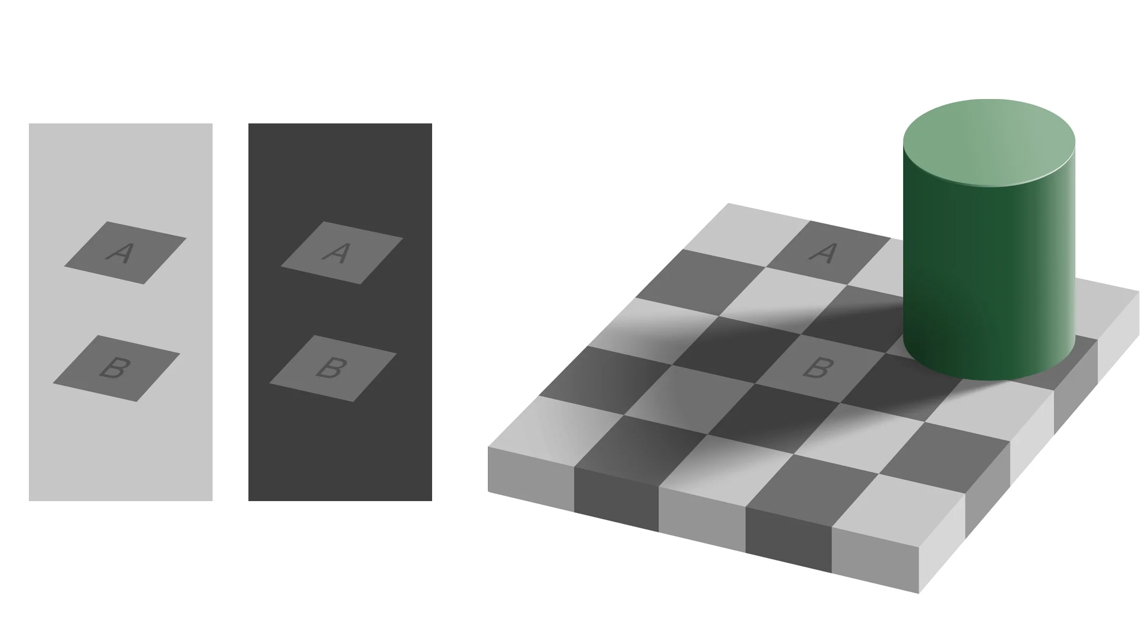
The infamous checker shadow illusion (credit: E. Adelson; license here). We added the gray sheet coming from the left to show that A and B really are the same color.
In reality, the squares are the same shade of gray.
Try It Yourself!
The gray value profile allows us to work more with numbers instead of visuals—in case our eyes really are deceiving us!
We can simply use the distance tool to set a line in one of the 2D views. The profile window shows a graph of gray values along that line.
Let's try this out on something quick and simple: a golf ball.
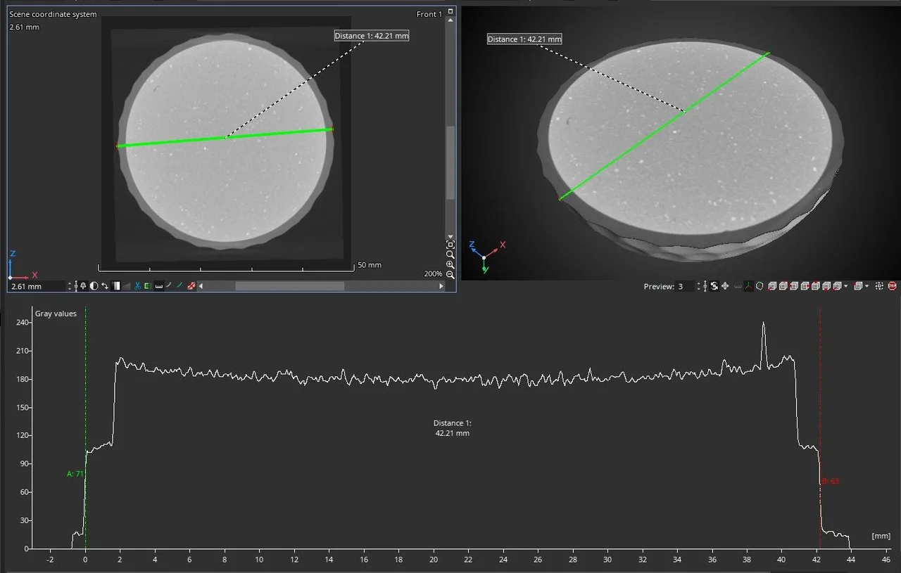
Dissecting a golf ball: we use the distance tool to set a line, and the profile window at the bottom of the screen shows us the gray values along that line
In this case, our eyes tell us that everything looks pretty good. However, if we look at the gray values, we can see a slight cupping effect caused by beam hardening. The outer edges of the core material are brighter (or rather, have higher gray values) than the center, which likely means that the scan or reconstruction was not done optimally.
Of course, not all profiles will look like this. Sometimes, artifacts in a data set—such as beam hardening—will cause more obvious distortions. Regardless of whether we can spot them, the profile window allows us to quantify these distortions.
Ready to Learn More?
Users of VGSTUDIO MAX can find out more about the different views and window layouts in the tutorials included in the software.
Got a Story?
If you have a VG Story to tell, let us know! Contact our Storyteller Team at: storytellers@volumegraphics.com. We look forward to hearing from you.
