
There Can Be Only One
It's inevitable: no matter how carefully we plan and prepare, each part will be produced with some form of manufacturing deviation. The tricky thing is, no two imperfections are quite the same. They may not affect the part in function, but it is good to have an idea of how real, manufactured parts behave—regardless of whether we have a CAD handy!
CAD-less endeavors are common in reverse engineering, which makes it a "golden" example for working with a real part. But if each part has even a slightly different deviation, how do we know which one is right for the job?
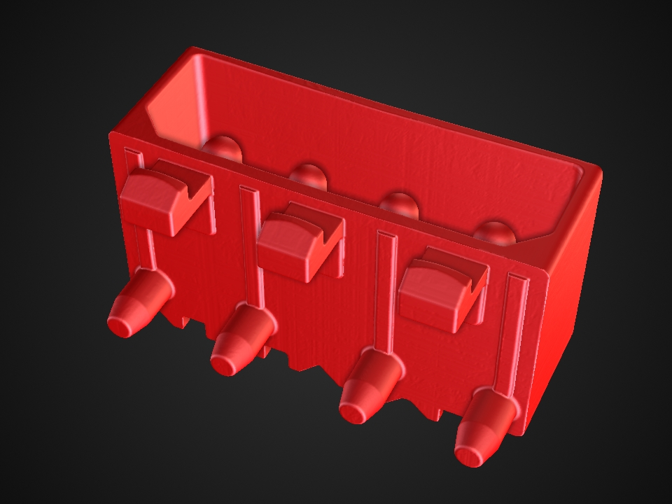
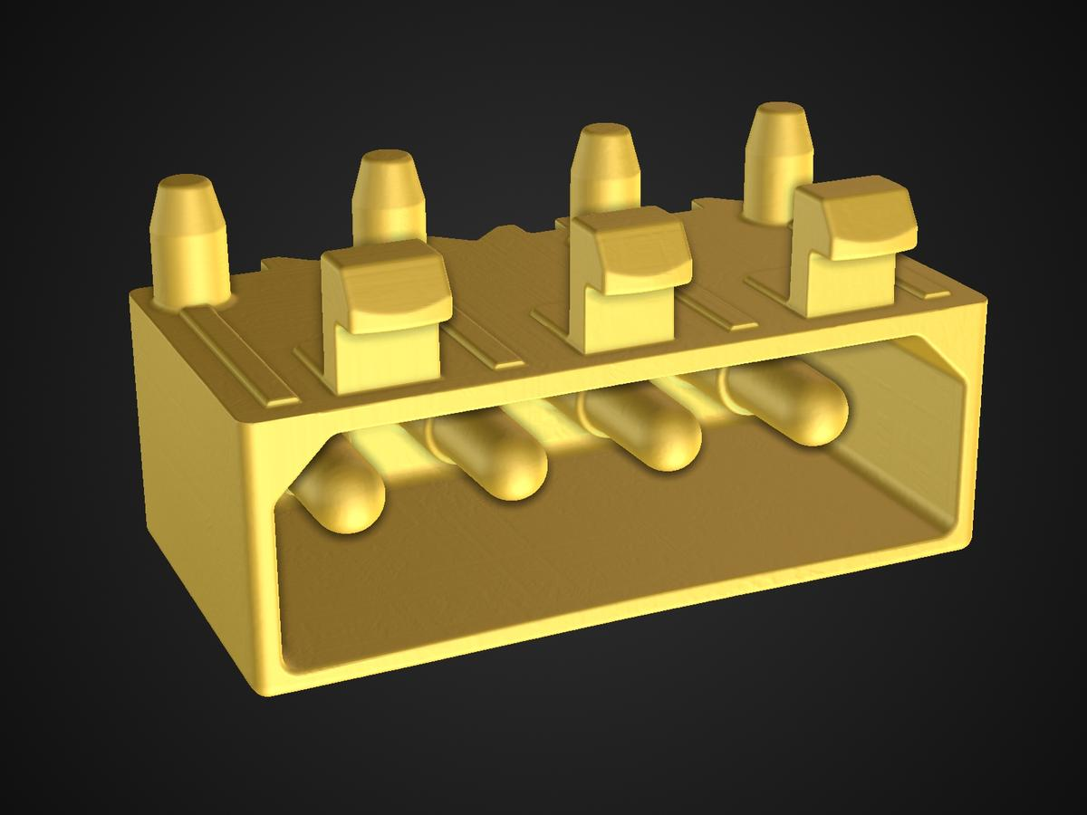
Seven different connectors—can you spot the differences?
The temptation to eyeball it is real. We can choose the one that looks good, right? But there is no method to this madness, and let's be honest—our eyes often deceive us.
This is where the golden surface comes in handy! Why take one part when we can take the average of all parts?
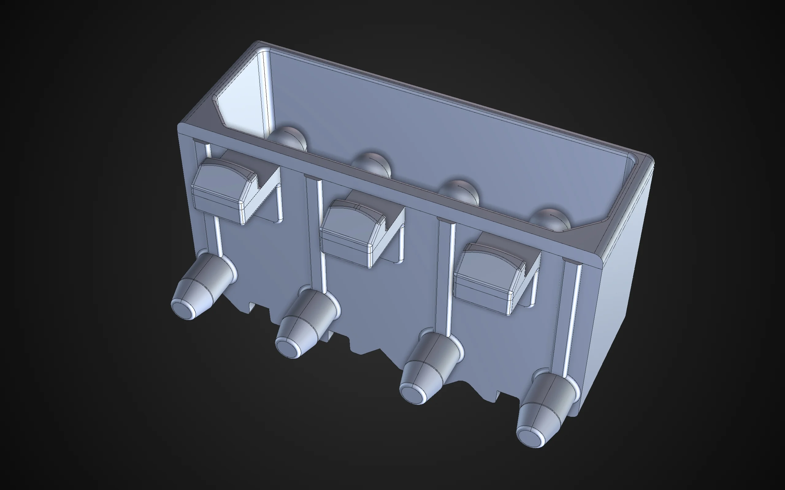
Let's take a closer look at this plastic connector. We have seven manufactured connectors, each with a slight deviation.
The Road to Perfection
Calculating the golden surface is handy for when we don't have a CAD model at the ready. We've mentioned reverse engineering, but a golden surface can also work with mesh compensation and manufacturing geometry correction.
Incidentally, if we do have a CAD, a golden surface is great for cases in which structurally weaker materials tend to change during their life cycle—such as plastic. Coincidentally, our seven connectors are made of plastic, and, after a bit of wear and tear, we do not know which one of them is closest to the nominal shape.
So let's calculate the golden surface!
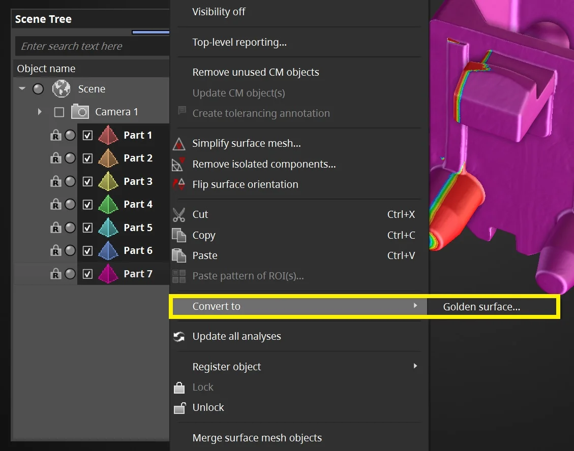
Select all the parts in the Scene Tree, right-click, and go to "Convert to" > "Golden surface..."
It's easy! Just select all the parts you want to average, right-click, and convert them to a golden surface.
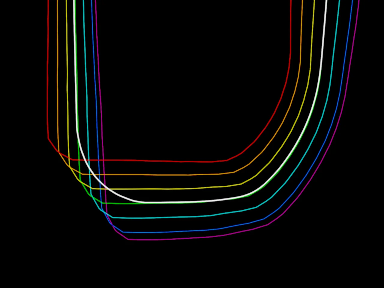
Seven (colorful) parts and the golden surface, represented by the thick white line
The golden surface in all its glory
By taking the average of manufactured parts, we stay on the safe side while ensuring that the results have a high chance of being close to the nominal shape.
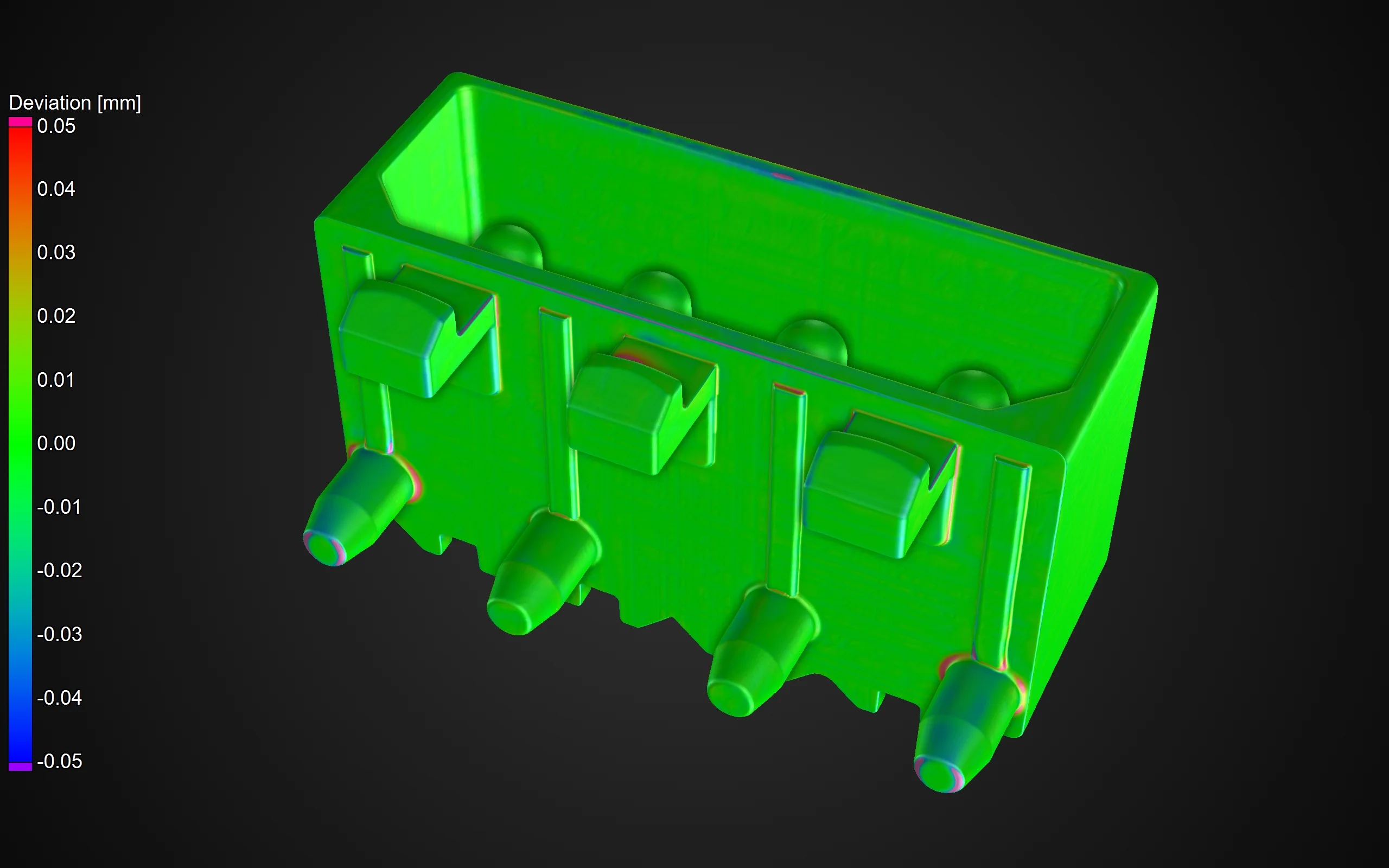
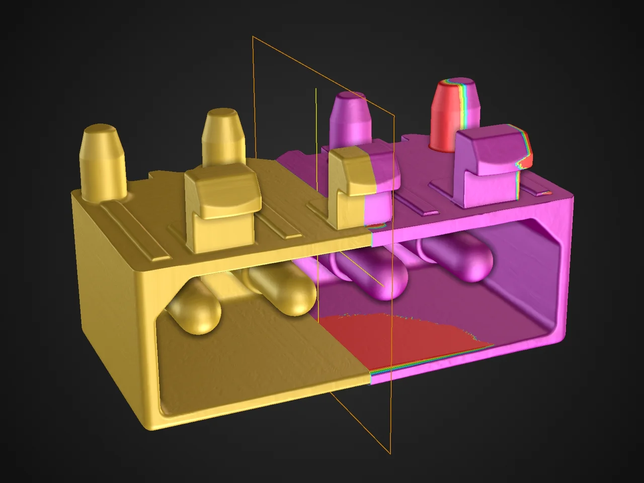
Comparing the golden surface to the nominal CAD, just to show how close the results are to the nominal shape
Golden Surfaces in Additive Manufacturing
Additive manufacturing is the perfect example for "imperfect" parts.
Say we want to 3D print our connector three times, but each part undergoes some form of shrinkage and turns out smaller than the nominal object. On top of that, the parts also differ slightly from one another!
In this case, we would rework the 3D model used for printing to avoid these deviations in the future and get our results as close as possible to the nominal part. But which of the three can we use?
Answer: all of them. Or rather, one of them. The golden one.
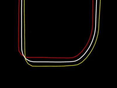
Step 1: Calculate the golden surface (white) from several parts that have undergone shrinkage
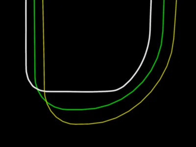
Step 2: Compensate the original mesh (green) using the golden surface. The resulting compensation is yellow
The next time you print the compensated mesh, the result will be closer to the nominal shape
Now that we have the golden surface and the nominal mesh, we can calculate the difference between the two and use the mesh compensation module to create a compensated mesh that accounts for the shrinkage. The golden surface should also be used for manufacturing geometry correction in the same manner.
Did You Know? Minimal and Maximal
In the golden surface dialog, there are two additional options called "minimal material" and "maximal material." They calculate the smallest and largest possible surface of all parts.
This comes in handy when we want to know how much two connecting parts can actually deviate while still fitting together.
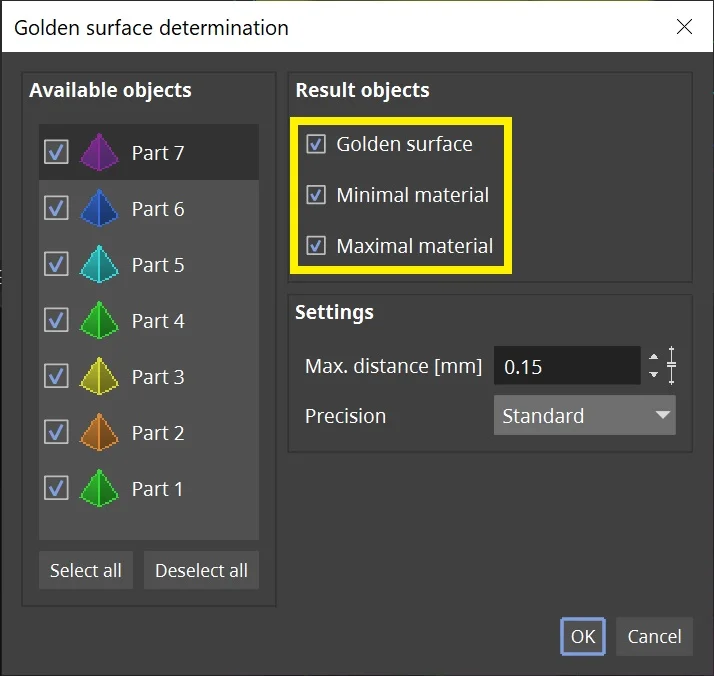
You can select all three options in the dialog
Ready to Learn More?
Users of VGSTUDIO MAX can find out more about golden surfaces and mesh compensation in the tutorials included in the software.
Got a Story?
If you have a VG Story to tell, let us know! Contact our Storyteller Team at: storytellers@volumegraphics.com. We look forward to hearing from you.
