
A Brief History of the Electric Motor
The Egger-Lohner C2 Phaeton—which looks rather like a horse-drawn relic from the olden days—is not quite the first electric racecar that comes to mind, but in September 1899, it won a 25-mile (40-km) road race in Berlin by a full 18 minutes. This model of electric vehicle was first developed in 1898 and ran on an octagonal electric motor—so named for the shape of its housing—at a top speed of 22 mph (35 km/h).

The 1898 Egger-Lohner C2 Phaeton model now stands in the Porsche Museum in Stuttgart—a relic of days past.
Of course, electric vehicles as we know them today are much faster and more efficient, with some even reaching speeds of 250 mph (400 km/h). However, while there is over a century separating modern cars from the Egger-Lohner, the same heart beats at the core of each vehicle: an electric motor.
The idea behind the electric motor has remained largely unchanged since its conception. Each motor consists of a spinning rotor and a stator mounted in the housing, which creates a magnetic field when a current flows through the windings. Rapidly changing magnetic fields create torque around the rotor’s axis and set it in constant motion, which generates the mechanical energy needed to turn the gears of the car. A crucial element in powering this rotation is the copper wires that comprise the stator’s internal coils. The first generation of electric motors used bundled coils with circular cross-sections.
However, this design has recently been optimized into hairpin winding technology. Unlike conventional round-wire winding, “hairpin” stators contain tightly packed, hairpin-shaped pieces of copper wire with rectangular cross-sections. Several layers of interlocking wires produce a superior slot fill, which drives higher sustained output, and the open ends of the wires are welded together to close the electric circuits. These high-precision hairpins ensure enhanced performance, continuous power flow, and high reproducibility.
This development has revolutionized the electric vehicle industry, and hairpin stators can now be found in virtually every electric vehicle.

Conventional round-wire windings

Modern bar windings greatly contrast conventional round-wire windings (above).
The Inspection Challenge
Of course, the switch from conventional round-wire winding to hairpin technology was such a leap that industries all over the world have been trying to fill the gaps—in more ways than one. Manufacturers of electric motors have a vested interest in ensuring the highest possible level of conductivity, which relies on hairpins having clean welds and low porosity at critical points. However, the welding joints at the ends of these hairpins are not quite as “seamless” as they seem. For one, since we are dealing with single-material hairpins, welding seams are not visible using X-ray technology, which makes quality inspection much more difficult; for another, they may contain pores introduced by the welding process, that reduce the cross-section area of the copper bar, which lowers the conductivity.
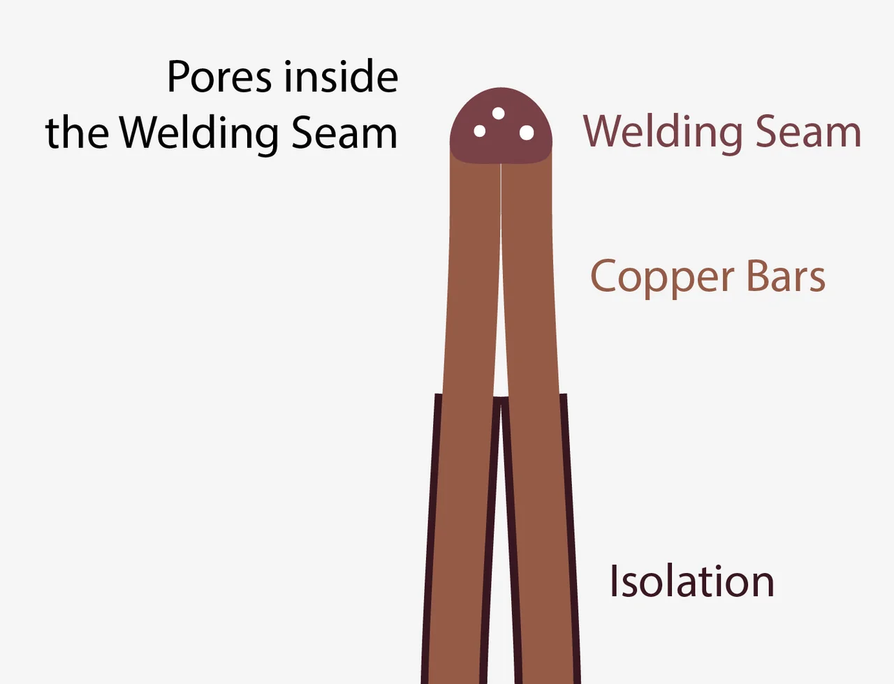
Image of a hairpin welding seam
At first glance, this may not seem to be a problem, but the time required to manually inspect these parts and make sure the pores won’t affect the quality of the engine can be quite costly. The solution? A fully automated approach that factors in the porosity of the welding seam! But of course, this is easier said than done. Because the welding process takes place after assembly, hairpins are always scanned along with the housing, which often leads to a lot of artifacts in the scan. Combined with the flexible, variable shape of the hairpins, this makes it nearly impossible to use a CAD model as a reference to align the object and get a clear idea of the hairpins in the stator.
Fortunately, there is a way to refine this inline process and drastically reduce the man-hours necessary for manual inspection.
Did You Know?
Follow the mouse clicks and start using the functionalities highlighted in the story today! We'll not only take you through the how, but also the when and why.
How to: Object Registration
DID YOU KNOW that you can also scan an object in parts and register them against a nominal CAD or mesh? Feature-based registration searches for similarities—think edges and other geometric features—and uses them as references against which the nominal object is aligned. This can also be useful if you scan your object in stages, such as if it is too long to scan in one go, and you want to align the scans with each other or even against a nominal object.

WHEN TO USE: Best-fit registration is better suited for aligning two objects that are similarly shaped—which is ideal if a CAD already represents the entire part. It starts by determining the center of gravity and aligns the object based on rotation until the surfaces match.
VG Solution
Porosity analysis is not a new solution by far, but with the subvoxel accuracy and refinement options offered by VGSTUDIO MAX, we can drastically improve the precision of the detected defect volume—as opposed to earlier methods in which the detection of a defect was only limited to voxel size. But what does this mean for hairpin technology in electric motors?

Detected pores in hairpin welding seams
As previously mentioned, the first major challenge is determining the welded section—especially since the top of the welding seam is round and cannot be seen on a CAD model. This requires aligning the object using a “golden” mesh—calculated from the average of several scans—and the region of interest (ROI) functionality to determine the analysis area. Because these meshes more accurately reflect the actual shape of the part, we can use registration to align the stator volume in each scan against this golden mesh. This lets us easily identify the analysis area and create an ROI pattern to define it.
Did You Know?
How to: Golden Surface
DID YOU KNOW that you can create a reference part if no CAD is available? In this case, you can create an average shape out of several scans of volume objects or surface meshes. This will ensure minimum deviations between parts.

1. Select the object(s) in the Scene Tree. Right-click to bring up the context menu and go to Convert to > Golden Surface.
2. Click OK.
WHEN TO USE: A “golden surface” creates an average shape out of several scans of a part. This ideal for plastics and other materials that may get deformed in production—like hairpins. It can also be used to reverse engineer an average shape so that random manufacturing deviations of single parts have less impact on the results. Creating a golden surface also allows for mesh compensation and manufacturing geometry correction.

After defining this analysis area, the second challenge is calculating and tolerancing the porosity of each welding seam. For this, the subvoxel-accurate VGEasyPore algorithm can be used on dedicated additional ROIs acquired by using CMM features while applying any defined tolerances based on the defect volume. Finally, using a projection mode approach gives us more accurate information on the remaining cross section for the current in the welding seam.

Inspecting the stator hairpins in VGSTUDIO MAX from three different angles and in 3D
By including the ROI functionality in the mix, we are able to acquire more accurate information on the hairpin. Based on our results, we can better automate the process, which saves us a lot of time by ensuring a seamless and reliable quality-control process without the need for manual inspection. Think about what that means: a much-needed coffee break, time to learn a new skill, or simply time to tackle that backlog that has been piling up since January. Automation can greatly reduce the analysis time and man-hours needed to inspect, produce, and manufacture critical parts in an electric engine.
Did You Know?
DID YOU KNOW about the relative mode in VGEasyPore? It offers subvoxel accuracy, which can give you greater insight into your object.
1. Start off by right-clicking the object and going to Create > Porosity/inclusion analysis > VGEasyPore.
2. Select “subvoxel” mode
3. Select “relative” mode from the drop-down list and adjust relative contrast as needed. Don’t forget to tick the “preview” checkbox so you can keep track of your adjustments before they even happen!
4. To refine subvoxel-accurate pores even more, check “defect refinement.” You can see the difference in the gif below:

Software Deep Dive
Relative mode in VGEasyPore is ideal for analyses run on a series of scans, especially if they are affected by artifacts or simple deviations in gray value caused by scanning time. This is because while fixed, absolute gray values can change, specifying percentages in relative mode will differ only slightly. This is—as the name suggests—a much more adaptive approach that can save time, reduce errors caused by scanner deviation, and more accurately reflect the actual defect area.
Another key timesaver to the workflow is the use of a golden surface, which basically acts as a reference part if no CAD is available. It is also useful for when produced parts are more similar among themselves than to their CAD model. In this case, an average object is created out of the scans of several stators, which reflects real-world situations much more accurately than a CAD. This “golden stator” serves as a standard against which stators are aligned for analysis. Based on this alignment, geometry elements were imported and used to align slices and create precise rectangular ROIs on the parts of interest—in this case, the hairpin welding seam—and used for porosity analysis.
Ready to Learn More?
Users of VGSTUDIO MAX can find out more about the different registration methods, golden surfaces, porosity analysis algorithms, and using ROIs in the tutorials included in the software.
If you are working in the EV industry and are ready to take the next step in automating your inspection processes, our consulting department is here for you! Please contact consulting@volumegraphics.com for more information.
Got a Story?
If you have a VG Story to tell, let us know! Contact our Storyteller Team at: storytellers@volumegraphics.com. We look forward to hearing from you.
