
We all have that one drawer chock-full of odd bolts and screws we've found lying around the house. It's always a mystery where they came from, especially when they assume so many shapes—flat heads, slotted heads, hexes, combination heads—and who can keep track of their many uses and dimensions? How can we figure out which screw we even need?
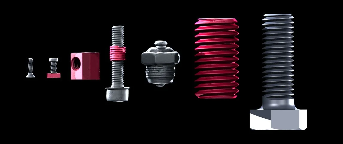
Flat heads and hexes and threads, oh my!
There is another unspoken, often overlooked hero to these screws—one that has both inner and outer threads: inserts. They make sure screws stay in place, or even more importantly, that the things they are holding stay in place. And by measuring the insert, we can also determine the screw we need.
Let's take a closer look at one!
Thread Carefully...
Threaded inserts, or bushings, are transition holes that are usually inserted into soft metals, such as aluminum, that hold screws securely in place. Without them, the soft metal gets worn down by both the hard steel of the screws and changing loads over time.
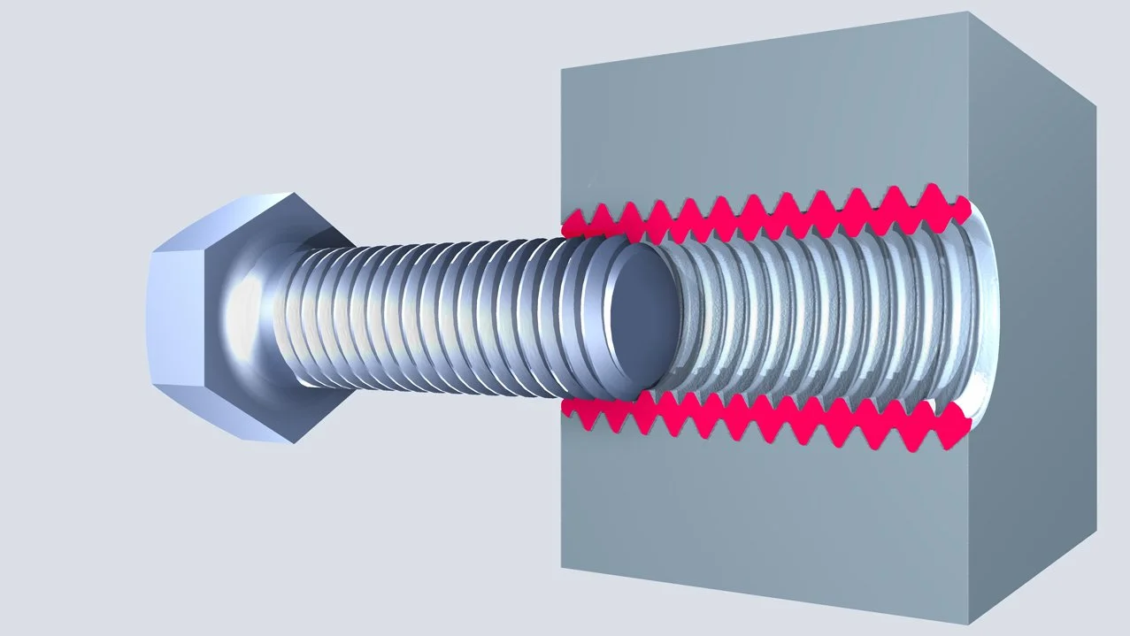
Depending on what it's holding in place, a faulty thread can be very dangerous. As such, inserts have inner and outer threads that need to meet tolerances.
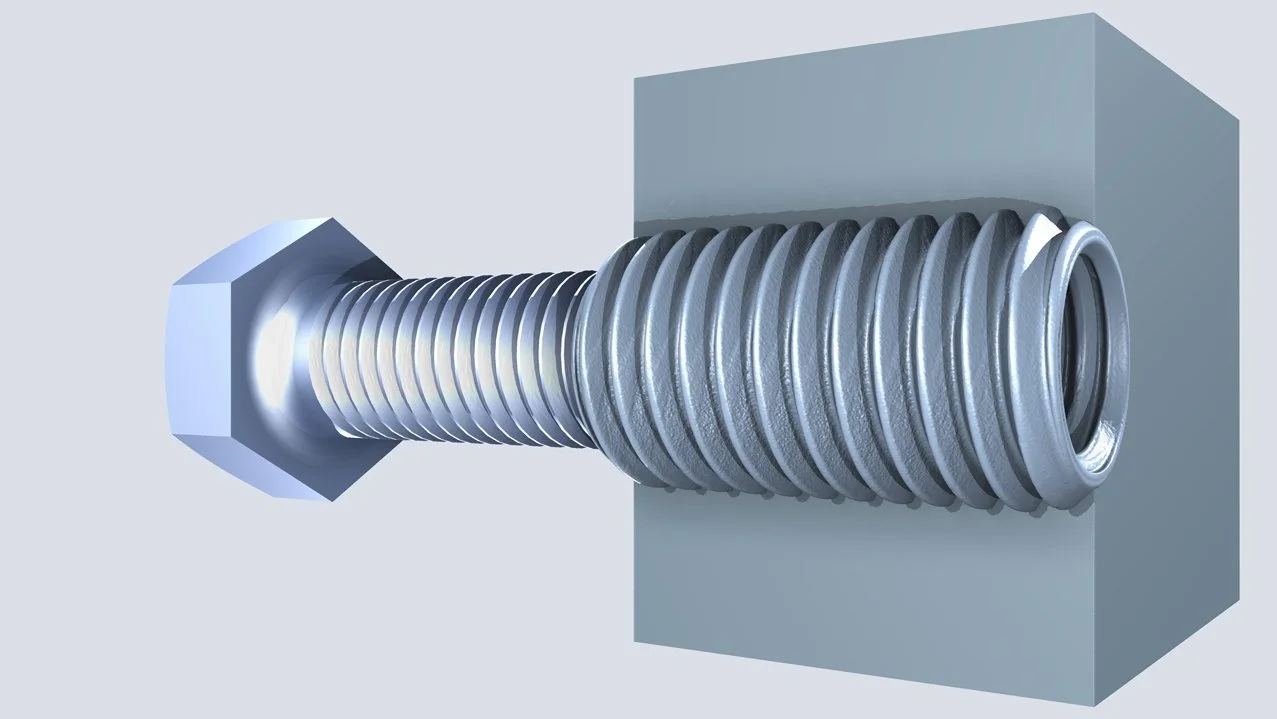
A thread insert, or "bushing," holds screws in place. Safety depends on the preciseness and stability of the threads
If our goal is to piece together the mystery of what screw we need, the angle and caliper or distance tool should suffice. But for quality inspection, we need a smarter, metrological approach.
But before we begin, as with all metrology-based quests, we need to start off with a quick surface determination. An advanced (classic) approach gives us a subvoxel-precise surface, one that is even more precise than a quick isovalue-based determination.
This allows us to easily fit cylinders along the shaft of the insert to measure diameter, calculate pitch, and determine the angle of the threads.
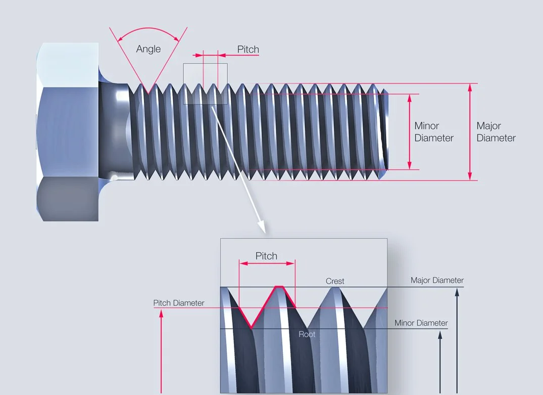
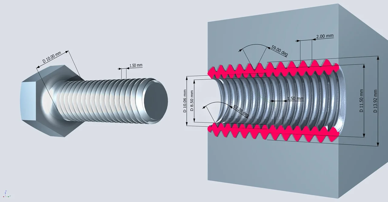
A quick visual reference of these terms
Two cylinders will be fit according to the outer crest and root—which requires minimum circumscribed fitting, as it considers the smallest cylinder based on the outermost fit point—and two others based on the inner crest and root of the insert, which calls for maximum inscribed to consider the largest cylinder based on the innermost fit point.
After that, there are a few other parameters to inspect, such as pitch—or the distance between grooves—and thread angle.
Let's focus on the pitch first.
The Windup... and the Pitch!
Measuring the pitch of a thread structure is a bit more complex. To start, we need to align the bolt along one of the axes in the coordinate system. Let's align slices to the cylinder, as it follows the shape of the insert.

Aligning slices to the cylinder
From there, we can define a line parallel to the cylinder axis that intersects the teeth along the pitch diameter—which is the middle point between our two fitted cylinders.
We can intersect this line with the surface we determined earlier to measure the pitch. In the case of our insert, the pitch of the outer thread is 2 mm. Since it intersects the complete thread, we can inspect the precision and consistency of the pitch along its entire length.

Measuring pitch: the average of these measurements is 2.00 mm
Quick note: if our goal is mass inspection, we need a stable, precise, and automated method, which we can do by aligning the parts against the CAD and applying a measurement template to the scanned parts.
Now let's turn our attention to the angle of the threads. While the industry standard of metric threads is 60°, let's make absolutely sure!
Capturing the Best Angle(s)
Thinking of the geometry of angles may be daunting, but the idea is simple enough: we fit two lines to the flanks—the lines connecting the crest and root—and measure the angle between them. However, if you are working with a CAD, there are a few other "points" to consider.
Lines in the CAD...
To create a line on the CAD, you may have to change the mode of point creation to either "single point" or "auto-expand." Otherwise, "CAD selection" will detect the whole face, create fit points on the intersection with the 2D slice, and attempt to fit a line based on these fit points. In other words, the results may be somewhat... unpredictable.
Both single-point and auto-expand give us more control over defining our line. Before finishing, don't forget to tick the "auto fit points" box to fill in fit points automatically.
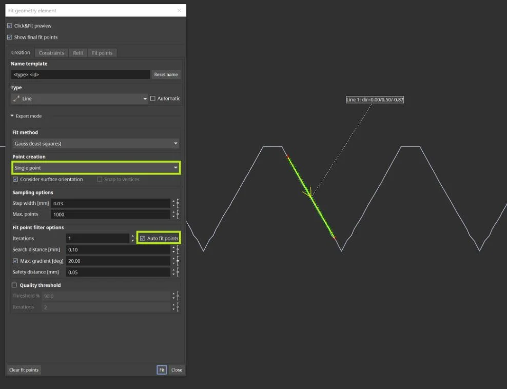
Single-point point creation is the best way to fit a line on a single flank
Once we have two lines set on two connecting flanks, we can select them and create an angle measurement with tolerances.
Done. Seems like a perfect fit.
Tying up Loose Threads
So we've just learned how to measure the ins and outs of a screw—literally! By applying tolerances, we can determine whether a thread meets the requirements or not.
Based on our measurements of the insert, we determined that the screw would have to be 10 mm in (major) diameter and have a pitch of 1.5 mm. That sounds conveniently like an M10x1.5 screw!
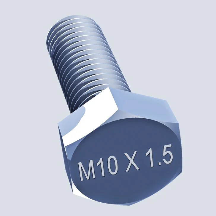
Case closed.
Ready to Learn More?
Users of VGSTUDIO MAX can find out more about metrology, alignment, and coordinate systems in the tutorials included in the software.
Got a Story?
If you have a VG Story to tell, let us know! Contact our Storyteller Team at: storytellers@volumegraphics.com. We look forward to hearing from you.
