This page is not compatible with Internet Explorer.
For security reasons, we recommend that you use an up-to-date browser, such as Microsoft Edge, Google Chrome, Safari, or Mozilla Firefox.
Tool Correction
Based on Industrial Computed Tomography
Tool Compensation for Shrinkage and Warpage in Injection Molding
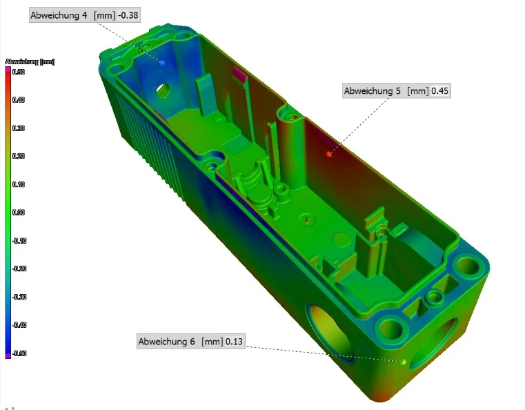
The typical molding defect is warpage. The material cool-down is not homogeneous due to the volume distribution and the filling process. Even with temperature management through complex 3D-printed cooling channels and simulation of the complete molding process, shrinkage and warpage of the final part occur. This is not the fault of the mold maker, but the result of the geometry, the material selection, and the mold design.
The Challenge
Translating the deformation information into actionable activities is difficult and includes the cooperation of several departments. If changes that have no influence on the geometry of the mold, like new injection points or changes in pressure and temperature, do not lead to a part in tolerance, a tool compensation optimizes the shape of the part.
To compensate for a molding defect like warpage, traditionally individual points are measured. Then the deviation is translated via a CAD software into compensated points, often including Excel and having metrology and design departments communicate with external service providers using analog information. Using different CAD packages and communication on paper instead of 3D information lead to several costly iteration cycles.
The Volume Graphics Solution: A Digital Workflow for Tool Correction
Volume Graphics speeds up the traditional workflow, but provides a lot more insight and possibilities. Instead of single points, complete surface information can be translated into compensated geometry and exported as CAD geometry to the mold maker.
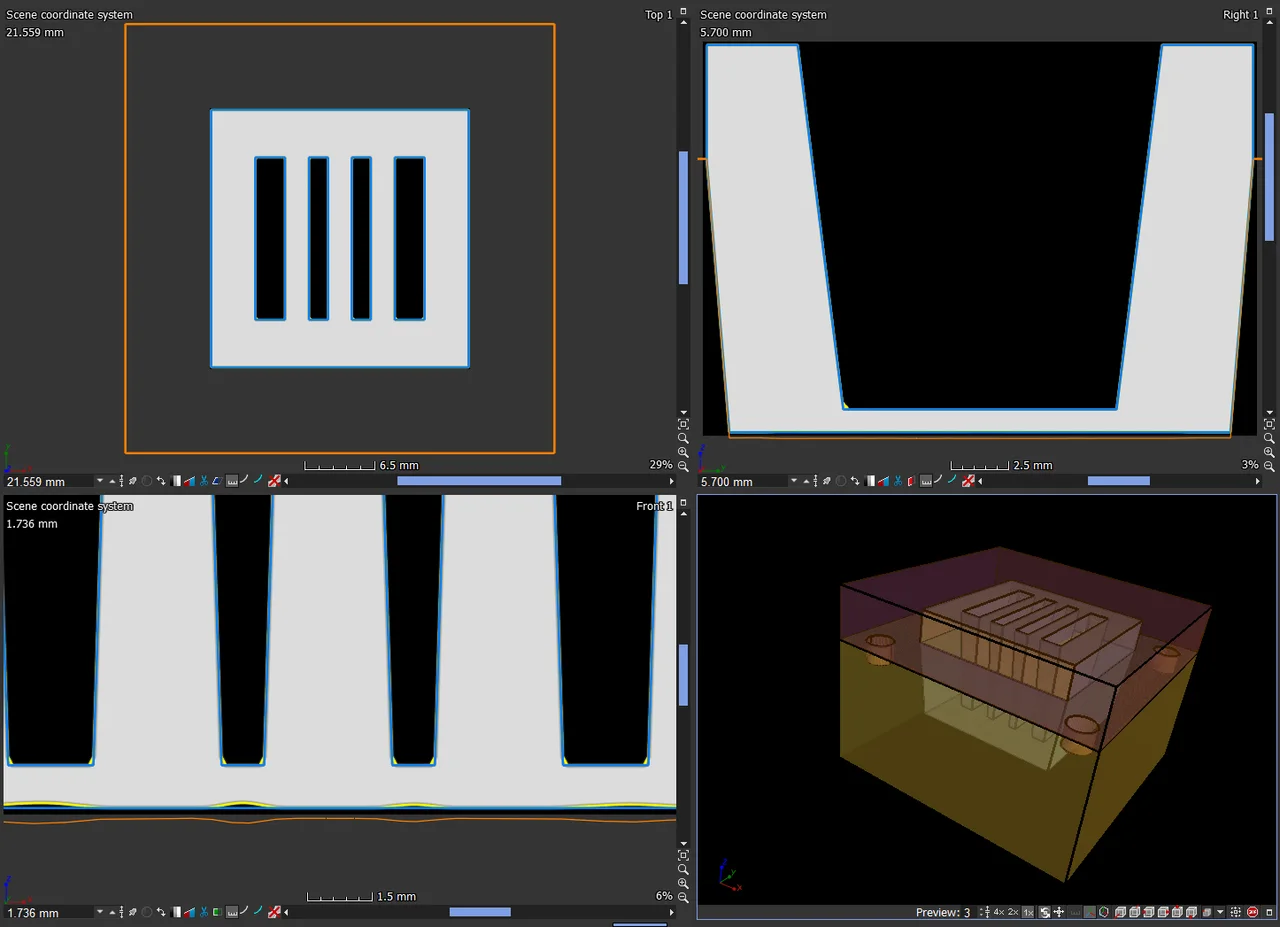
The Manufacturing Geometry Correction Module (MGC) helps lowering the number of iterations needed to create a mold that produces parts in tolerance. MGC uses industrial computed tomography (CT) or optical scans of your sample part to precisely calculate necessary changes to injection molds, punching tools, or geometries of 3D-printed parts and to create a tool correction. By analyzing the effect of different alignments, it is possible to minimize the update cost of the mold.
The user has full control of the complexity and quality of the compensated surface areas and can analyze both curvature quality and draft situation.
The corrections take all details of the part and the mold, shrinkage and warpage into account without the need for elaborate inspection or reverse engineering workflows. Quickly and easily export information about the newly calculated surfaces directly as CAD surfaces—and thus create an optimal part/mold fit in just a few steps. A simulation mesh can be used as an input as well, helping to create the first iteration of the mold.
The manufacturing geometry correction provides a seamless interaction in neutral formats between the design and measurement departments and the mold maker. All in the same software.

Advantages
Volume Graphics gives you an easy-to-use tool that yields straightforward results and integrates seamlessly into your workflow:
Cost Saving
Cost Saving
- Reduces iterations in mold making
- Direct 3D communication between metrology and mold making
- Quick optimization of mold geometry
- Faster time to market
User Friendly
User Friendly
- One software for metrology and tool correction on both CT and mesh data
- Single, user-friendly interface
- Easy to learn
- Little training needed
Versatile
Versatile
- Works for injection molding, casting, 3D printing and sheet metal forming
- Handles CAD, point cloud, mesh (also simulation), and voxel data
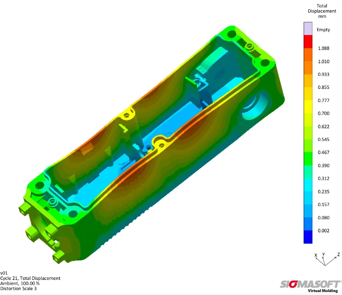
Simulation of molding process
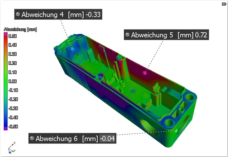
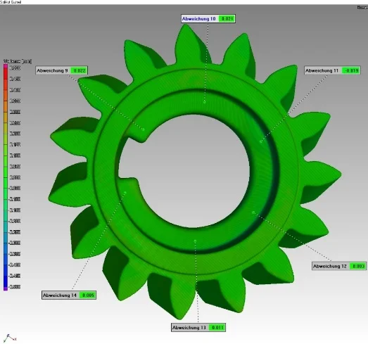
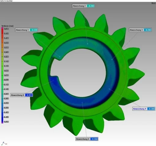
First article inspection of initial design iteration
Inspection of part from compensated and updated mold
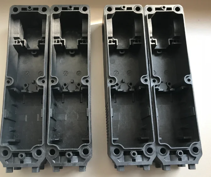
Initial deformed part (left) and part in tolerance from optimized mold (right)

Surface reconstruction: Update the master CAD model, create a CAD model of the actual part including warpage

Surface compensation: Compensate for warpage, also for 3D printed parts
Tool compensation: Compensated tool areas are ready for export to a CAD system