
In the Beginning...
Traditional testing methods are not capable of detecting complex inner geometries and surface shapes. Its rigid nature makes customizations challenging and time-consuming, which makes it difficult to avoid extra costs and meet production deadlines.
Additive manufacturing, on the other hand, is an innovative method that is optimized to work with intricate shapes and a wide range of materials, such as plastics, composites, and metals. But even in the world of 3D printing, some options are better than others—the possibilities are endless. Where do we even begin?
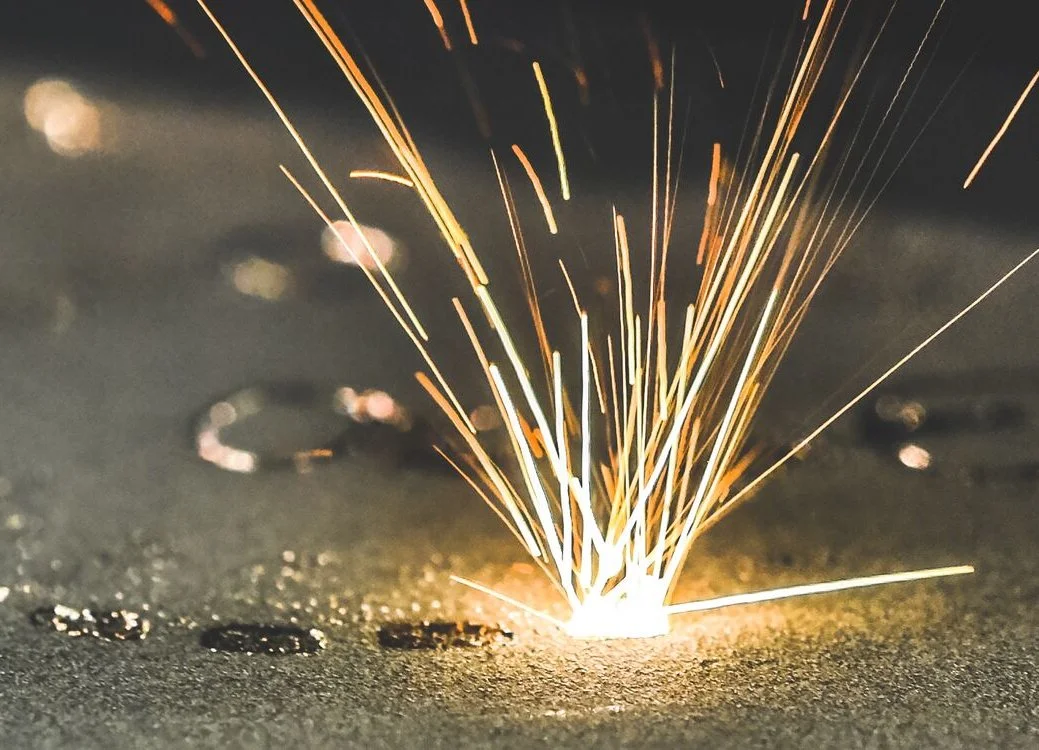
The gritty details of metal 3D printed parts: an object is printed on a 3D printer for metal and covered in metallic powder. (Credit: Photostock)
Let's join Fraunhofer IWS as they compare the precision of different 3D printing technologies and materials!
Ready...
The contenders among additive manufacturing technologies are Laser Powder Bed Fusion (L-PBF) and Electron Beam Powder Bed Fusion (E-PBF). These were selected as worthy candidates for their high precision and ability to print metal.
The materials were Ti6Al4V and AlSi40, which will be printed using L-PBF, and Ti5553, which will be printed via E-PBF.
These materials were chosen because of their relevance in the aerospace, space, and energy sectors. In particular, Ti5553 is a special alloy for high-stressed parts with higher tensile and yield strength compared to Ti6Al4V.
The titanium variants will be provided by Agent3D, and AlSi40 will be provided by the ESA.

This 3D-printed turbine blade is a great example of a high-stressed part. (Credit: Photostock)
Set...
At first glance, the challenge is simple: the team 3D-modelled a special part to include a variety of features that could pose challenges to additive manufacturing, such as holes and pins of varying diameters, complex surfaces and channels, and thin, overhanging surfaces.

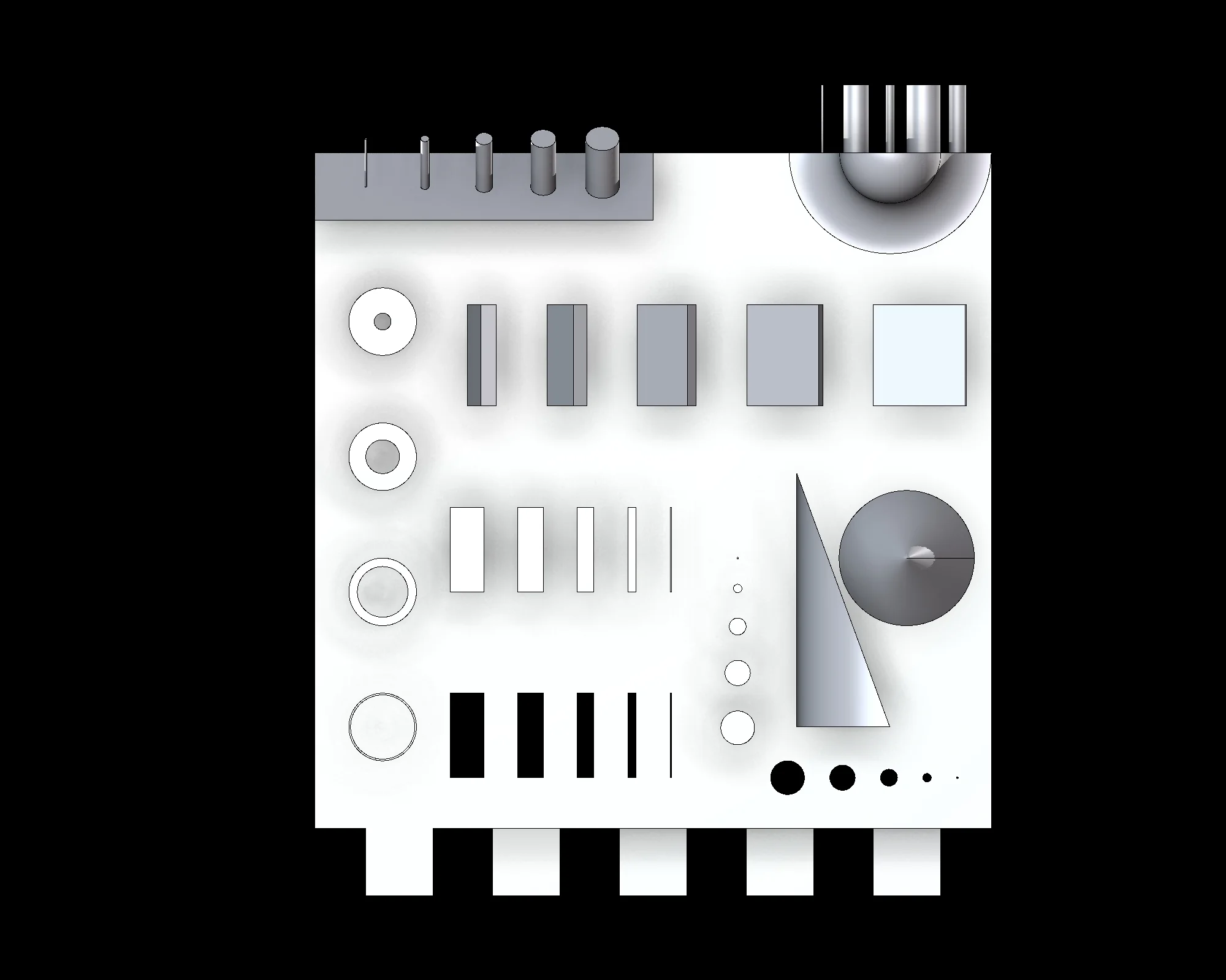
A labeled diagram of what features were included in the special part (credit: "Evaluation of 3D-Printed Parts by Means of High-Performance Computer Tomography," conference paper)
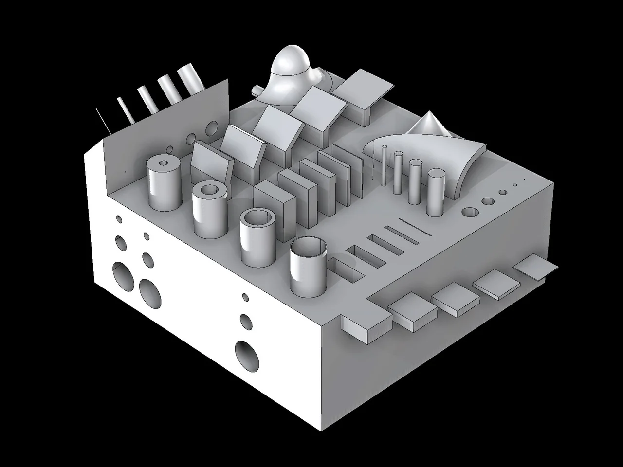
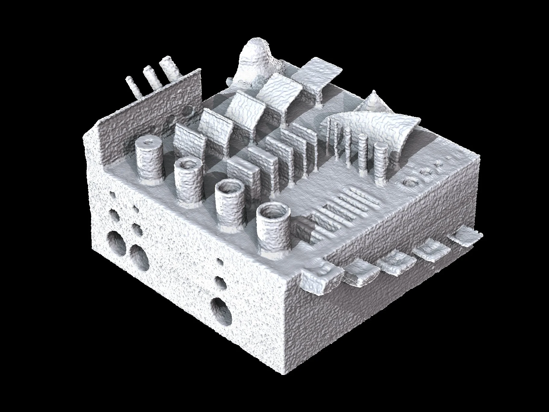
Rendering of the 3D model
Several versions of the test part will be printed using each contender.
...Go!
Here are the results of 3D printing using L-PBF technology:
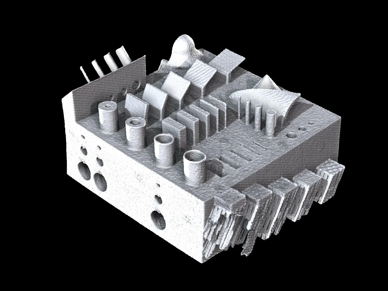
Printing Ti6Al4V. Most of the thin structures were preserved after printing
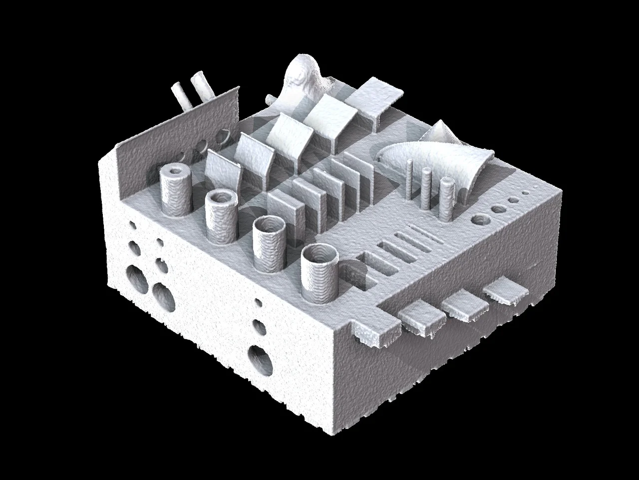
Printing AlSi40. The quality is superior, but fewer thin structures were printed
Here are the results of 3D printing using E-PBF technology:
3D Printing Technologies
Laser Powder Bed Fusion (L-PBF) is a process that takes place in a chamber with a controlled atmosphere of inert gas. A source of heat (in this case, a laser) scans the metal powder bed based on a CAD model and melts layer after layer of the metal. After a metal layer is processed, the powder bed moves down, and a rake adds a new layer of powder. The laser selectively melts the metal powder where solid material is needed. For this test, a Renishaw AM 250 was used.
Electron Beam Power Bed Fusion (E-PBF) has a similar approach, as it also works layer by layer, but it diverges on the power source. Instead of a laser, EBM uses a high-energy electron beam powered by a high voltage under a vacuum atmosphere, which makes it well suited for reactive materials with a high affinity to oxygen. For this test, an Arcam A2X was used.
Laser sintering machine for metal. (Credit: Photostock)
Evaluating the Parts
Because the part includes internal channels, CT is the preferred method for inspection as opposed to optical scanning. It results in a fully digitized object that makes it easier to evaluate the quality of each printed part and obtain highly accurate information, such as wall thickness, porosities, cracks, and inclusions.
After scanning, each part was compared to its nominal CAD model.
Nominal/Actual Comparison
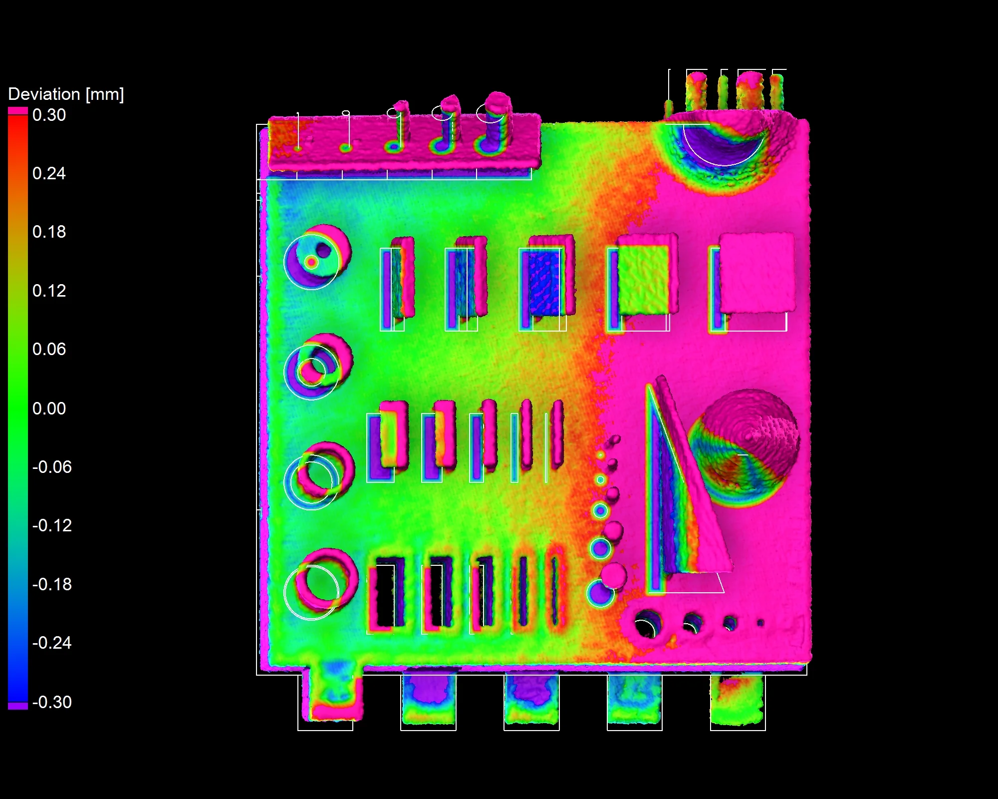
A nominal/actual comparison is designed to compare data sets and CAD models to each other. It provides a detailed report on deviations as well as a color-coded data set for future reference.
Here are the comparison results of 3D printing using L-PBF technology:

Ti6Al4V + nominal/actual comparison vs. CAD
AlSi40 + nominal/actual comparison vs. CAD
Here are the results of 3D printing using E-PBF technology:

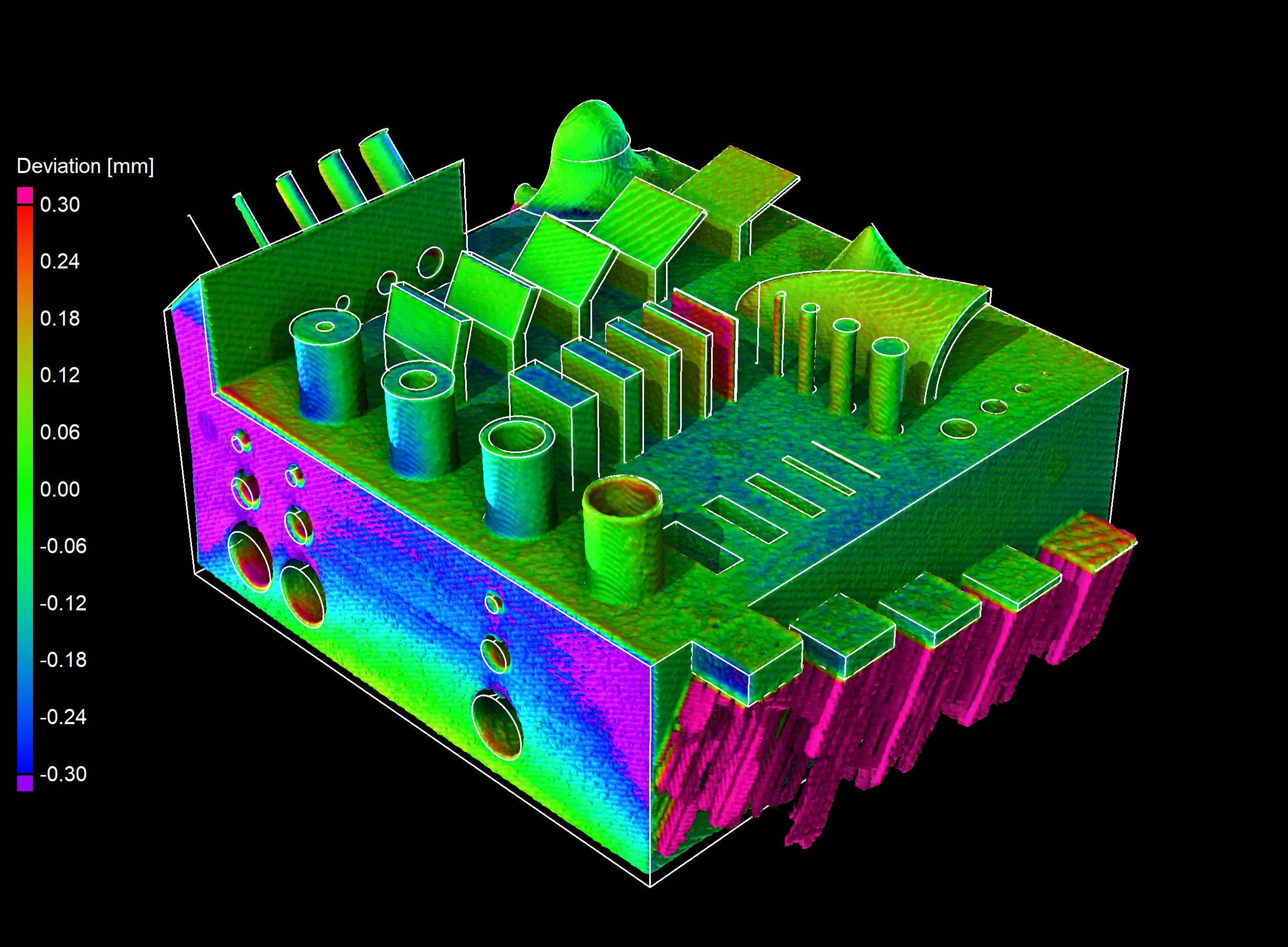
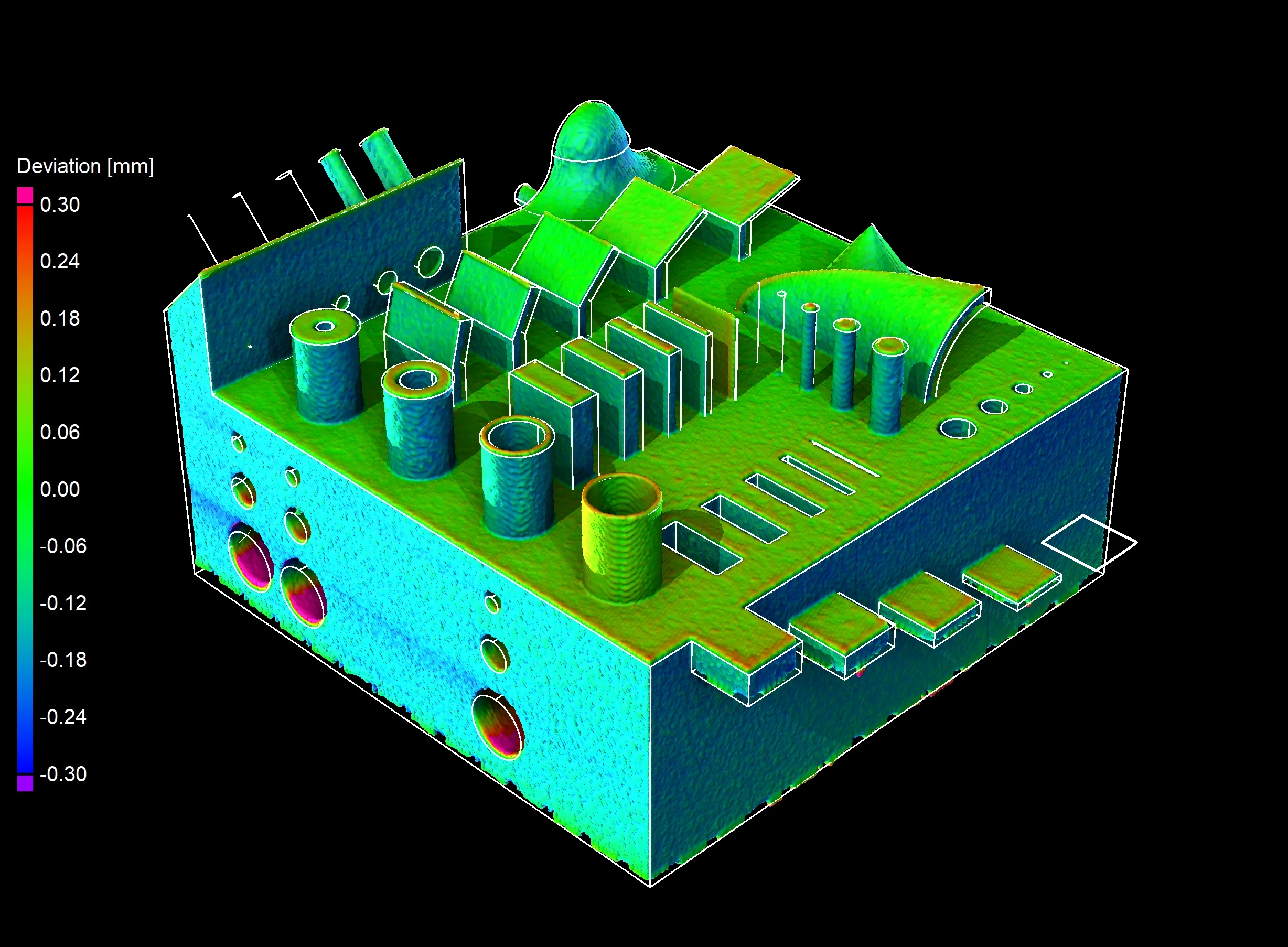
Ti5553 + nominal/actual comparison vs. CAD
We can use different modes to specify the resolution of the comparison. For example, Quality keeps the resolution the same as that of the data set, while Performance resolution is lower. Preview also allows us to get a quick visual impression of the comparison using a fixed resolution, regardless of data set resolution.
We can also set annotations for minimum and maximum deviations as well as tolerance possibilities, which gives us a quick and easy overview of what needs further inspection in the part.
Did You Know? Components in a Nominal/Actual Comparison
Working with components allows us to set a deviation interval and examine areas of the part that fall within this range.
We can also change the interval mode to further specify permissible values. For example, "outside" calculates deviations below the lower, and above the upper limit, while "inside" calculates values within the range. We can set the mode to "left" if we only want deviations below the lower limit, and to "right" if we want deviations above the upper limit.
Quick tip: if you only want to examine areas that fall under the specified component conditions, simply tick "show components only" in the "colors" tab of the analysis.
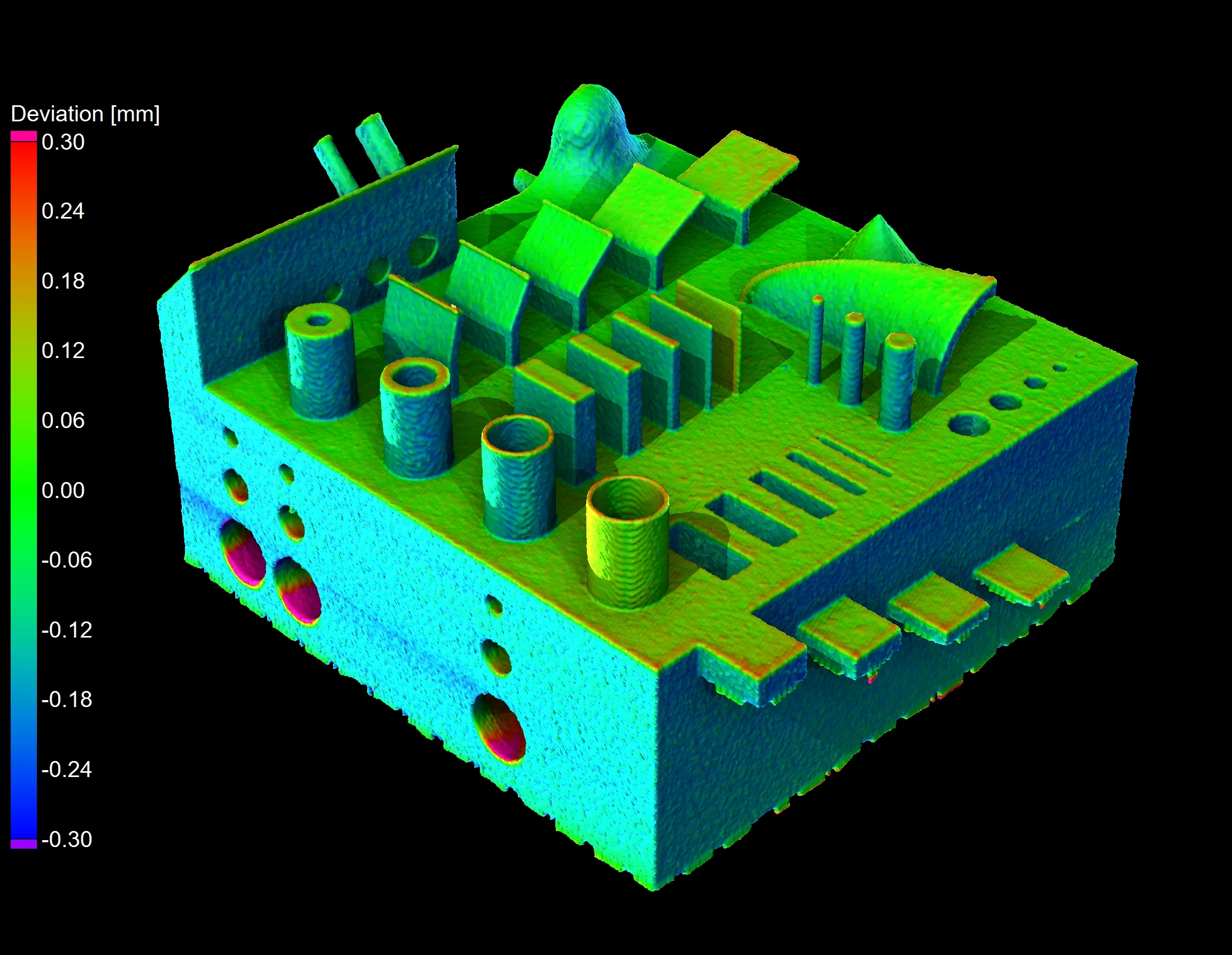
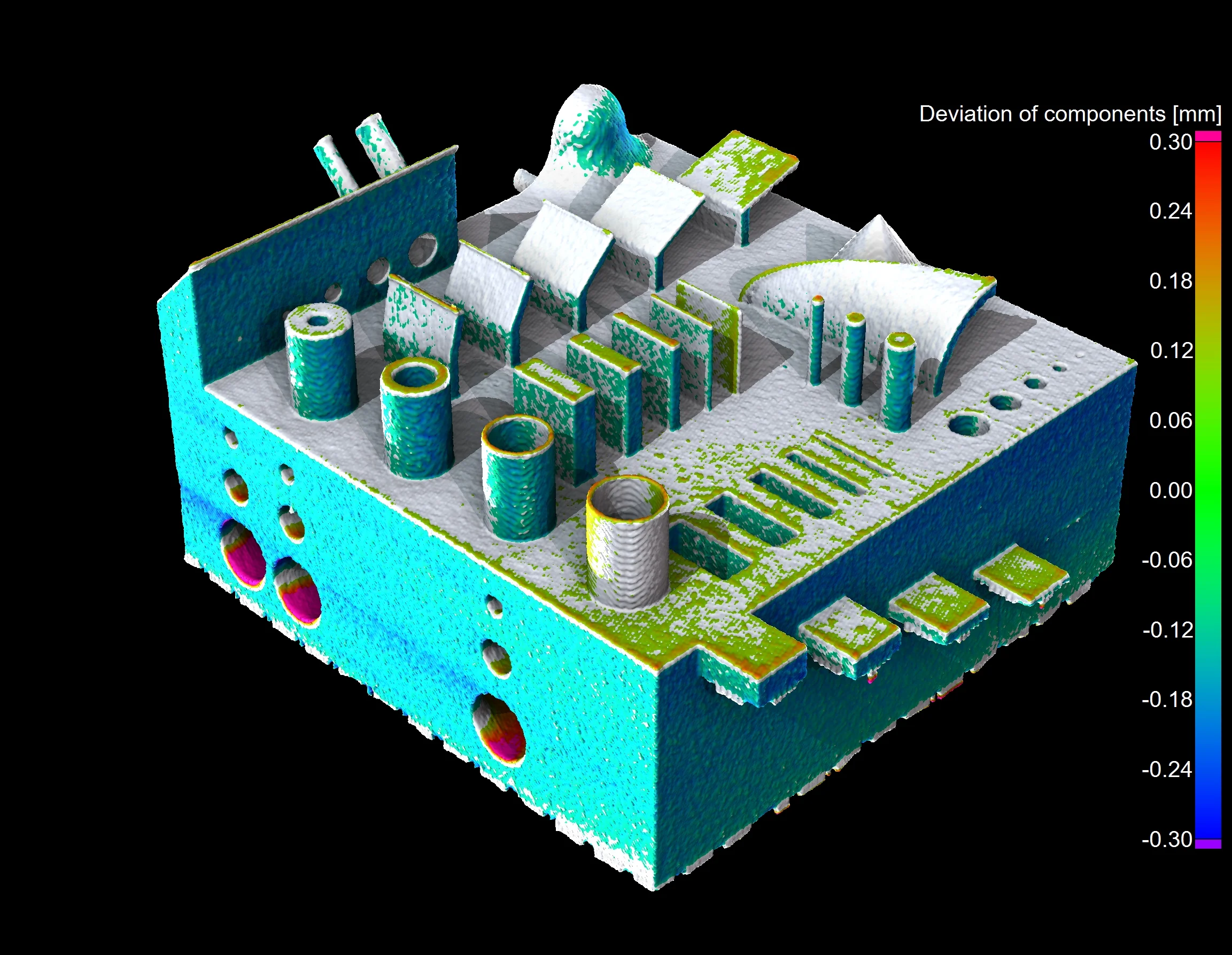
All deviations vs. deviations of components only
The Results
3D-printed parts using E-PBF did not accurately reproduce the features of the part. CT analysis revealed swelling in the Z-direction as well as retraction around the part. The excessive building temperature of the beam resulted in sintering in the internal channels. Deviations ran quite high, but they did not affect the nominal/actual comparison results for the outer surfaces.
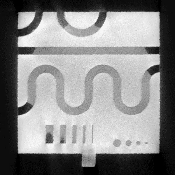
Stuck powder in Ti5553 (highlighted in red)
3D-printed parts using L-PBF revealed a superior capability to reproduce intricate details and higher geometrical accuracy, but this was only possible with AlSi40, likely due to its higher melting temperature, which allows for greater melt pool control.
Parts printed with Ti6Al4V had low deviations, though it could not reproduce very thin wall structures without warpage (and even detaching from the support structure entirely). These parts also suffered residual powder, which obstructed the internal channels.
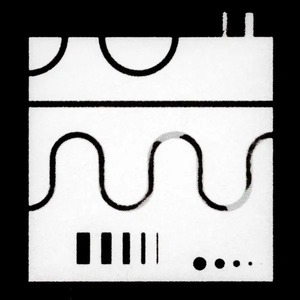
Stuck powder in AlSi40 (highlighted in red)
The Judges' Verdict
With the help of CT technology and VGSTUDIO MAX, researchers determined that Laser Powder Bed Fusion (L-PBF) is more capable of reproducing fine details and higher geometrical accuracy compared to Electron Beam Powder Bed Fusion (E-PBF). However, producing parts with a tolerance inferior to ±0.5 appears to be its limit, as its accuracy is heavily material-dependent.
E-PBF is slightly faster, and all layers are preheated during the printing process. This makes it more suitable for materials that are susceptible to cracks, since the heating process prevents cracking. However, it does not as accurate as L-PBF and cannot produce such fine details.
Epilogue: The Power of Mesh Compensation
But what if the part is overdeformed after printing?
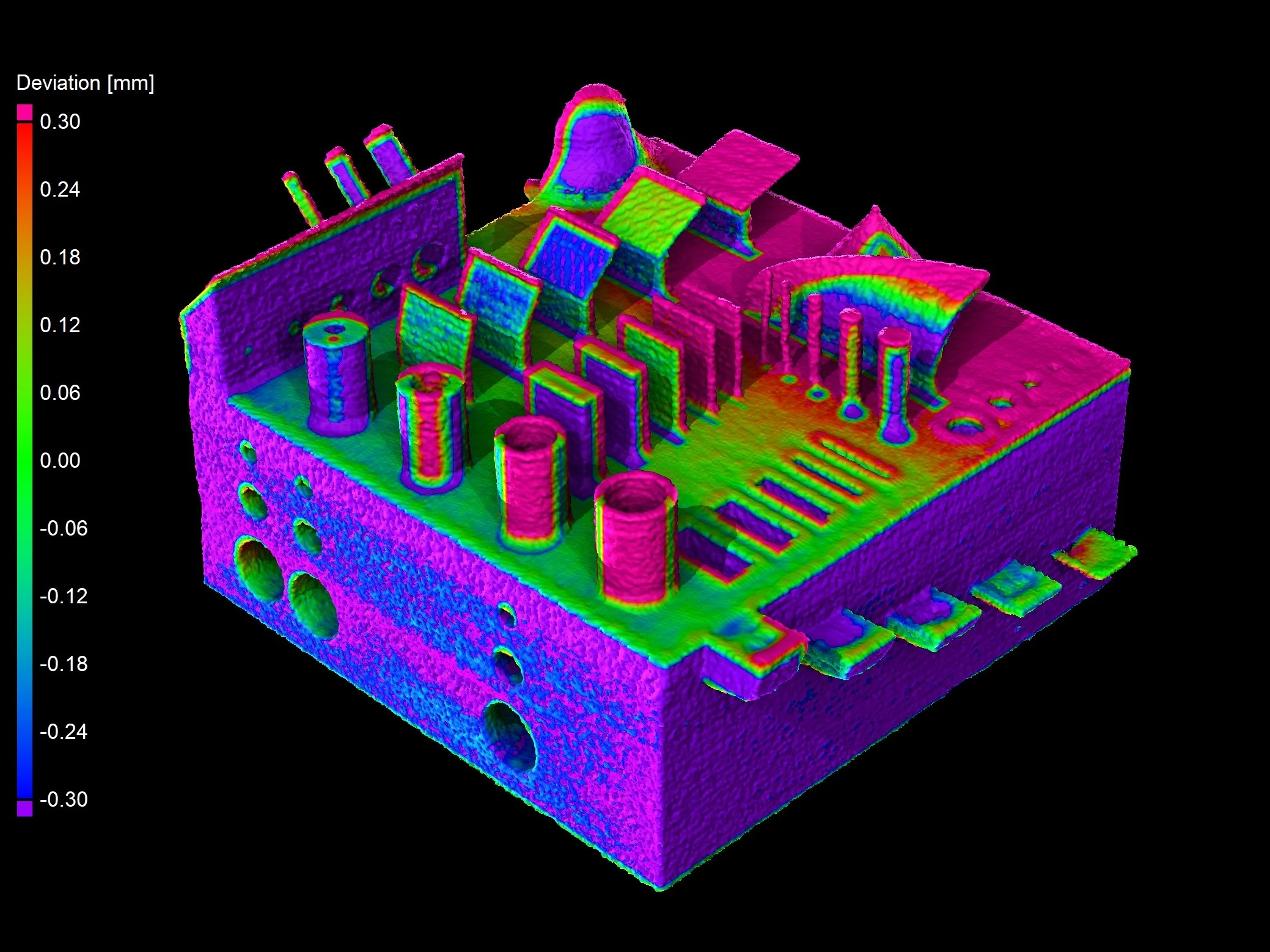
If we take a closer look at the nominal/actual comparison, such as the that of the Ti5553 material used in the L-PBF method, we see that the deviations are severe, and we see that some elements of the part have shifted drastically.
Despite this, the comparison shows some green areas on the shifted elements’ surfaces. In short, we know that the element has somehow “sailed” away, but the nominal/actual comparison still shows a few green areas, which indicates a good match between the nominal and actual object—even if the rest of the part is bright red.
Nominal/actual comparison shows green areas despite overall severe warping
The reason for this match is that a nominal/actual comparison tries to match the closest surfaces of nominal and actual objects, and if any area of the nominal surface matches the local actual surface, the result is green.
While green is generally a good thing, how can we get more accurate results that take into more drastic deviations?
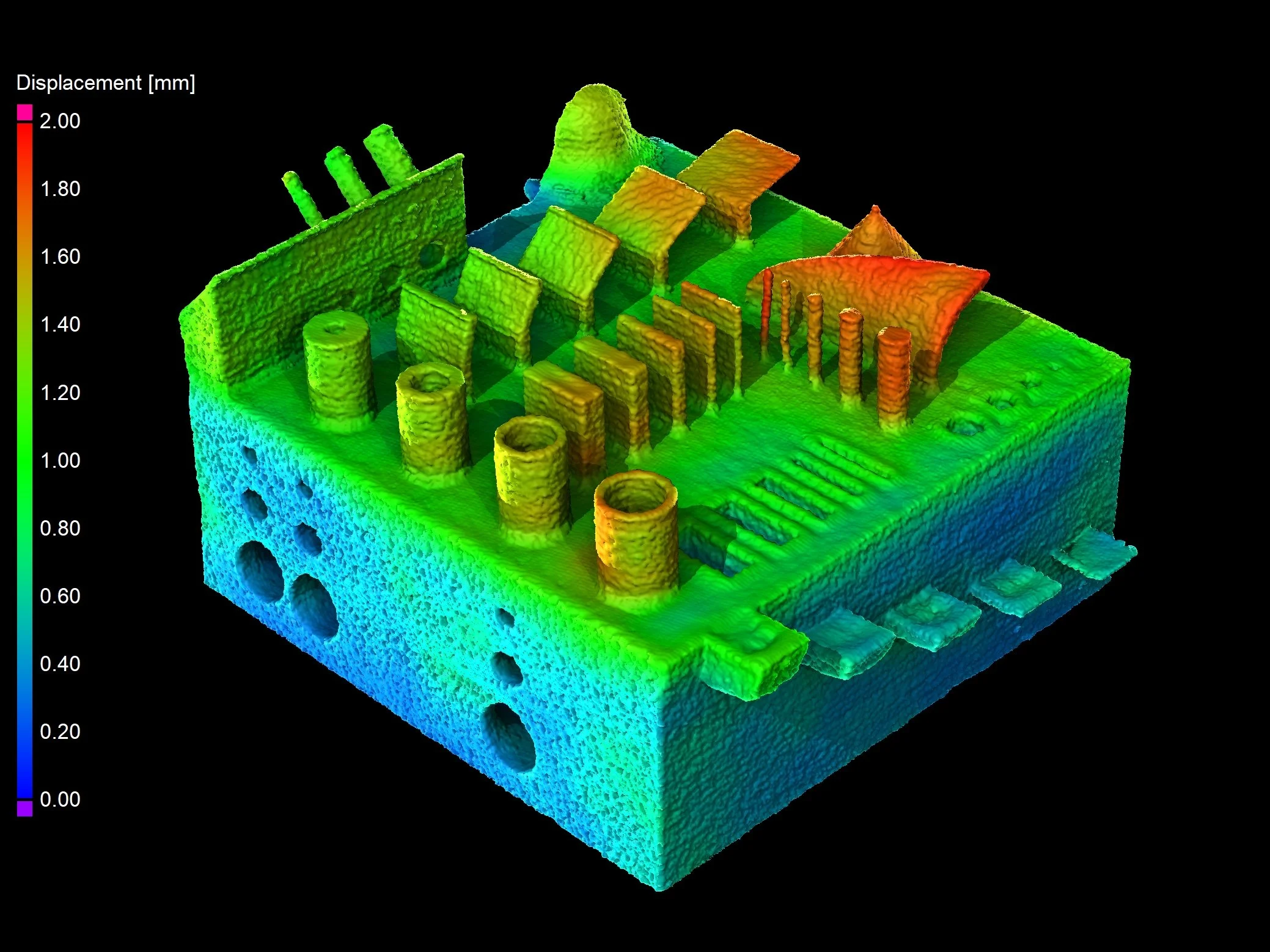
For this, we can turn to mesh compensation! It uses a matrix of control points and calculates displacement for each point in space. This results in a color map that describes the morphing of the part. Based on that, a compensated mesh can be generated to create a more precise part geometry with the next iteration.

Matrix of control points used by mesh compensation

Displacement vectors of mesh compensation
Nominal/actual comparison (left) vs. mesh compensation (right)
Ready to Learn More?
Users of VGSTUDIO MAX can find out more about nominal/actual comparisons, visualization, and rendering in the tutorials included in the software.
Got a Story?
If you have a VG Story to tell, let us know! Contact our Storyteller Team at: storytellers@volumegraphics.com. We look forward to hearing from you.
